Example for Configuring an IPv6 over IPv4 GRE Tunnel
Networking Requirements
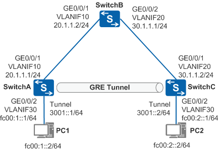
In Figure 1, SwitchA and SwitchC on IPv6 networks connect to SwitchB on an IPv4 public network. PC1 and PC2 on the two IPv6 networks need to communicate with each other.
PC1 uses SwitchA and PC2 uses SwitchC as a default gateway.
Configuration Roadmap
To allow PC1 and PC2 on IPv6 networks to communicate with each other across an IPv4 network, you can configure a direct link between SwitchA and SwitchC to set up a GRE tunnel and configure a static route to forward packets through tunnel interfaces to the peer.
The configuration roadmap is as follows:
Configure IP addresses for physical interfaces and configure an IPv4 static route to implement interworking over the IPv4 network.
Create tunnel interfaces on SwitchA and SwitchC to set up a GRE tunnel, and configure an IPv6 static route passing through tunnel interfaces on SwitchA and SwitchC, so that traffic between PC1 and PC2 can be transmitted over the GRE tunnel.
Procedure
- Configure an IP address for each physical interface.
# Configure SwitchA.
<HUAWEI> system-view
[HUAWEI] sysname SwitchA
[SwitchA] vlan batch 10 30
[SwitchA] interface gigabitethernet 0/0/1
[SwitchA-GigabitEthernet0/0/1] port link-type trunk
[SwitchA-GigabitEthernet0/0/1] port trunk allow-pass vlan 10
[SwitchA-GigabitEthernet0/0/1] quit
[SwitchA] interface gigabitethernet 0/0/2
[SwitchA-GigabitEthernet0/0/2] port link-type access
[SwitchA-GigabitEthernet0/0/2] port default vlan 30
[SwitchA-GigabitEthernet0/0/2] quit
[SwitchA] interface vlanif 10
[SwitchA-Vlanif10] ip address 20.1.1.1 24
[SwitchA-Vlanif10] quit
[SwitchA] ipv6
[SwitchA] interface vlanif 30
[SwitchA-Vlanif30] ipv6 enable
[SwitchA-Vlanif30] ipv6 address fc00:1::1 64
[SwitchA-Vlanif30] quit
# Configure SwitchB.
<HUAWEI> system-view
[HUAWEI] sysname SwitchB
[SwitchB] vlan batch 10 20
[SwitchB] interface gigabitethernet 0/0/1
[SwitchB-GigabitEthernet0/0/1] port link-type trunk
[SwitchB-GigabitEthernet0/0/1] port trunk allow-pass vlan 10
[SwitchB-GigabitEthernet0/0/1] quit
[SwitchB] interface gigabitethernet 0/0/2
[SwitchB-GigabitEthernet0/0/2] port link-type trunk
[SwitchB-GigabitEthernet0/0/2] port trunk allow-pass vlan 20
[SwitchB-GigabitEthernet0/0/2] quit
[SwitchB] interface vlanif 10
[SwitchB-Vlanif10] ip address 20.1.1.2 24
[SwitchB-Vlanif10] quit
[SwitchB] interface vlanif 20
[SwitchB-Vlanif20] ip address 30.1.1.1 24
[SwitchB-Vlanif20] quit
# Configure SwitchC.
<HUAWEI> system-view
[HUAWEI] sysname SwitchC
[SwitchC] vlan batch 20 30
[SwitchC] interface gigabitethernet 0/0/1
[SwitchC-GigabitEthernet0/0/1] port link-type trunk
[SwitchC-GigabitEthernet0/0/1] port trunk allow-pass vlan 20
[SwitchC-GigabitEthernet0/0/1] quit
[SwitchC] interface gigabitethernet 0/0/2
[SwitchC-GigabitEthernet0/0/2] port link-type access
[SwitchC-GigabitEthernet0/0/2] port default vlan 30
[SwitchC-GigabitEthernet0/0/2] quit
[SwitchC] interface vlanif 20
[SwitchC-Vlanif20] ip address 30.1.1.2 24
[SwitchC-Vlanif20] quit
[SwitchC] ipv6
[SwitchC] interface vlanif 30
[SwitchC-Vlanif30] ipv6 enable
[SwitchC-Vlanif30] ipv6 address fc00:2::1 64
[SwitchC-Vlanif30] quit
- Enable the service loopback function on an Eth-Trunk
# Configure SwitchA.
[SwitchA] interface eth-trunk 1
[SwitchA-Eth-Trunk1] service type tunnel
[SwitchA-Eth-Trunk1] quit
[SwitchA] interface gigabitethernet 0/0/3
[SwitchA-GigabitEthernet0/0/3] eth-trunk 1
[SwitchA-GigabitEthernet0/0/3] quit
# Configure SwitchC.
[SwitchC] interface eth-trunk 1
[SwitchC-Eth-Trunk1] service type tunnel
[SwitchC-Eth-Trunk1] quit
[SwitchC] interface gigabitethernet 0/0/3
[SwitchC-GigabitEthernet0/0/3] eth-trunk 1
[SwitchC-GigabitEthernet0/0/3] quit
- Configure an IPv4 static route.
# Configure SwitchA.
[SwitchA] ip route-static 30.1.1.0 255.255.255.0 20.1.1.2# Configure SwitchC.
[SwitchC] ip route-static 20.1.1.0 255.255.255.0 30.1.1.1 - Configure a tunnel interface.
# Configure SwitchA.
[SwitchA] interface tunnel 1
[SwitchA-Tunnel1] tunnel-protocol gre
[SwitchA-Tunnel1] ipv6 enable
[SwitchA-Tunnel1] ipv6 address 3001::1 64
[SwitchA-Tunnel1] eth-trunk 1
[SwitchA-Tunnel1] source 20.1.1.1
[SwitchA-Tunnel1] destination 30.1.1.2
[SwitchA-Tunnel1] quit
# Configure SwitchC.
[SwitchC] interface tunnel 1
[SwitchC-Tunnel1] tunnel-protocol gre
[SwitchC-Tunnel1] ipv6 enable
[SwitchC-Tunnel1] ipv6 address 3001::2 64
[SwitchC-Tunnel1] eth-trunk 1
[SwitchC-Tunnel1] source 30.1.1.2
[SwitchC-Tunnel1] destination 20.1.1.1
[SwitchC-Tunnel1] quit
- Configure a static tunnel route.
# Configure SwitchA.
[SwitchA] ipv6 route-static fc00:2:: 64 tunnel 1
# Configure SwitchC.
[SwitchC] ipv6 route-static fc00:1:: 64 tunnel 1
- Verify the configuration.
# Ping the IPv4 address of SwitchA from SwitchC. SwitchC can receive a Reply packet from SwitchA.
[SwitchC] ping 20.1.1.1
  PING 20.1.1.1: 56  data bytes, press CTRL_C to break
    Reply from 20.1.1.1: bytes=56 Sequence=1 ttl=254 time=84 ms
    Reply from 20.1.1.1: bytes=56 Sequence=2 ttl=254 time=27 ms
    Reply from 20.1.1.1: bytes=56 Sequence=3 ttl=254 time=25 ms
    Reply from 20.1.1.1: bytes=56 Sequence=4 ttl=254 time=3 ms
    Reply from 20.1.1.1: bytes=56 Sequence=5 ttl=254 time=24 ms

  --- 20.1.1.1 ping statistics ---
    5 packet(s) transmitted
    5 packet(s) received
    0.00% packet loss
    round-trip min/avg/max = 3/32/84 ms
# Ping the IPv6 address of SwitchA from SwitchC. SwitchC can now receive a Reply packet from SwitchA.
[SwitchC] ping ipv6 fc00:1::1
  PING fc00:1::1 : 56  data bytes, press CTRL_C to break
    Reply from FC00:1::1
    bytes=56 Sequence=1 hop limit=64  time = 28 ms
    Reply from FC00:1::1
    bytes=56 Sequence=2 hop limit=64  time = 27 ms
    Reply from FC00:1::1
    bytes=56 Sequence=3 hop limit=64  time = 26 ms
    Reply from FC00:1::1
    bytes=56 Sequence=4 hop limit=64  time = 27 ms
    Reply from FC00:1::1
    bytes=56 Sequence=5 hop limit=64  time = 26 ms

  --- fc00:1::1 ping statistics ---
    5 packet(s) transmitted
    5 packet(s) received
    0.00% packet loss
round-trip min/avg/max = 26/26/28 ms
Configuration Files
-
#
sysname SwitchA
#
ipv6
#
vlan batch 10 30
#
interface Vlanif10
 ip address 20.1.1.1 255.255.255.0
#
interface Vlanif30
 ipv6 enable
 ipv6 address FC00:1::1/64
#
interface Eth-Trunk1
 service type tunnel
#
interface GigabitEthernet0/0/1
 port link-type trunk
 port trunk allow-pass vlan 10
#
interface GigabitEthernet0/0/2
 port link-type access
 port default vlan 30
#
interface GigabitEthernet0/0/3
 eth-trunk 1
#
interface Tunnel1
 ipv6 enable
 ipv6 address 3001::1/64
 tunnel-protocol gre
 source 20.1.1.1
 destination 30.1.1.2
 eth-trunk 1
#
ip route-static 30.1.1.0 255.255.255.0 20.1.1.2
#
ipv6 route-static FC00:2:: 64 Tunnel1
#
return
-
#
sysname SwitchB
#
vlan batch 10 20
#
interface Vlanif10
 ip address 20.1.1.2 255.255.255.0
#
interface Vlanif20
 ip address 30.1.1.1 255.255.255.0
#
interface GigabitEthernet0/0/1
 port link-type trunk
 port trunk allow-pass vlan 10
#
interface GigabitEthernet0/0/2
 port link-type trunk
 port trunk allow-pass vlan 20
#
return
-
#
sysname SwitchC
#
ipv6
#
vlan batch 20 30
#
interface Vlanif20
 ip address 30.1.1.2 255.255.255.0
#
interface Vlanif30
 ipv6 enable
 ipv6 address FC00:2::1/64
#
interface Eth-Trunk1
 service type tunnel
#
interface GigabitEthernet0/0/1
 port link-type trunk
 port trunk allow-pass vlan 20
#
interface GigabitEthernet0/0/2
 port link-type access
 port default vlan 30
#
interface GigabitEthernet0/0/3
 eth-trunk 1
#
interface Tunnel1
 ipv6 enable
 ipv6 address 3001::2/64
 tunnel-protocol gre
 source 30.1.1.2
 destination 20.1.1.1
 eth-trunk 1
#
ip route-static 20.1.1.0 255.255.255.0 30.1.1.1
#
ipv6 route-static FC00:1:: 64 Tunnel1
#
return