Example for Configuring Basic IS-IS Functions
Networking Requirements
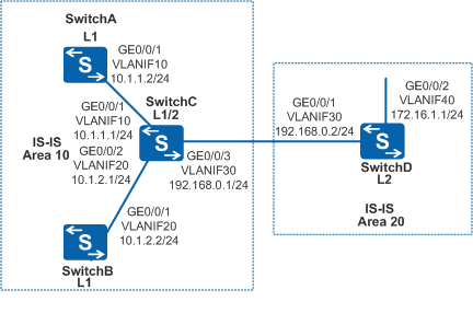
As shown in Figure 1, there are four switches (SwitchA, SwitchB, SwitchC, and SwitchD) on the network. The four switches need to communicate with each other. SwitchA and SwitchB can only process a small amount of data because they have lower performance than the other two switches.
Configuration Roadmap
The configuration roadmap is as follows:
Enable IS-IS on each switch so that the switches can be interconnected. Configure SwitchA and SwitchB as Level-1 devices to enable them to maintain less data.
Procedure
- Create VLANs and add corresponding interfaces to the VLANs.
# Configure SwitchA. The configurations of SwitchB, SwitchC, and SwitchD are similar to the configuration of SwitchA.
<HUAWEI> system-view
[HUAWEI] sysname SwitchA
[SwitchA] vlan batch 10
[SwitchA] interface gigabitethernet 0/0/1
[SwitchA-GigabitEthernet0/0/1] port link-type trunk
[SwitchA-GigabitEthernet0/0/1] port trunk allow-pass vlan 10
[SwitchA-GigabitEthernet0/0/1] quit
- Assign an IP address to each VLANIF interface.
# Configure SwitchA. The configurations of SwitchB, SwitchC, and SwitchD are similar to the configuration of SwitchA.
[SwitchA] interface vlanif 10
[SwitchA-Vlanif10] ip address 10.1.1.2 24
[SwitchA-Vlanif10] quit
- Run the IS-IS progress on each Switch, specify the network entity
title, and configure the level.
# Configure SwitchA.
[SwitchA] isis 1
[SwitchA-isis-1] is-level level-1
[SwitchA-isis-1] network-entity 10.0000.0000.0001.00
[SwitchA-isis-1] quit
# Configure SwitchB.
[SwitchB] isis 1
[SwitchB-isis-1] is-level level-1
[SwitchB-isis-1] network-entity 10.0000.0000.0002.00
[SwitchB-isis-1] quit
# Configure SwitchC.
[SwitchC] isis 1
[SwitchC-isis-1] network-entity 10.0000.0000.0003.00
[SwitchC-isis-1] quit
# Configure SwitchD.
[SwitchD] isis 1
[SwitchD-isis-1] is-level level-2
[SwitchD-isis-1] network-entity 20.0000.0000.0004.00
[SwitchD-isis-1] quit
- Enable the IS-IS progress on each interface.
# Configure SwitchA.
[SwitchA] interface vlanif 10
[SwitchA-Vlanif10] isis enable 1
[SwitchA-Vlanif10] quit
# Configure SwitchB.
[SwitchB] interface vlanif 20
[SwitchB-Vlanif20] isis enable 1
[SwitchB-Vlanif20] quit
# Configure SwitchC.
[SwitchC] interface vlanif 10
[SwitchC-Vlanif10] isis enable 1
[SwitchC-Vlanif10] quit
[SwitchC] interface vlanif 20
[SwitchC-Vlanif20] isis enable 1
[SwitchC-Vlanif20] quit
[SwitchC] interface vlanif 30
[SwitchC-Vlanif30] isis enable 1
[SwitchC-Vlanif30] quit
# Configure SwitchD.
[SwitchD] interface vlanif 30
[SwitchD-Vlanif30] isis enable 1
[SwitchD-Vlanif30] quit
[SwitchD] interface vlanif 40
[SwitchD-Vlanif40] isis enable 1
[SwitchD-Vlanif40] quit
- Verify the configuration.
# View the IS-IS LSDB of each Switch.
[SwitchA] display isis lsdb

                        Database information for ISIS(1)
                        --------------------------------

                          Level-1 Link State Database

LSPID                 Seq Num      Checksum      Holdtime      Length  ATT/P/OL
-------------------------------------------------------------------------------
0000.0000.0001.00-00* 0x0000006e   0x953e        862           68      0/0/0
0000.0000.0002.00-00  0x0000006a   0xc015        766           68      0/0/0
0000.0000.0002.01-00  0x00000008   0xccb6        766           55      0/0/0
0000.0000.0003.00-00  0x00000086   0x529e        1155          111     1/0/0
0000.0000.0003.01-00  0x0000005e   0xf238        1155          55      0/0/0

Total LSP(s): 5
    *(In TLV)-Leaking Route, *(By LSPID)-Self LSP, +-Self LSP(Extended),
           ATT-Attached, P-Partition, OL-Overload
[SwitchB] display isis lsdb

                        Database information for ISIS(1)
                        --------------------------------

                          Level-1 Link State Database

LSPID                 Seq Num      Checksum      Holdtime      Length  ATT/P/OL
-------------------------------------------------------------------------------
0000.0000.0001.00-00  0x0000006e   0x953e        899           68      0/0/0
0000.0000.0002.00-00* 0x0000006a   0xc015        808           68      0/0/0
0000.0000.0002.01-00* 0x00000008   0xccb6        808           55      0/0/0
0000.0000.0003.00-00  0x00000086   0x529e        1195          111     1/0/0
0000.0000.0003.01-00  0x0000005e   0xf238        1195          55      0/0/0

Total LSP(s): 5
    *(In TLV)-Leaking Route, *(By LSPID)-Self LSP, +-Self LSP(Extended),
           ATT-Attached, P-Partition, OL-Overload
[SwitchC] display isis lsdb

                        Database information for ISIS(1)
                        --------------------------------

                          Level-1 Link State Database

LSPID                 Seq Num      Checksum      Holdtime      Length  ATT/P/OL
-------------------------------------------------------------------------------
0000.0000.0001.00-00  0x0000006e   0x953e        953           68      0/0/0
0000.0000.0002.00-00  0x0000006a   0xc015        859           68      0/0/0
0000.0000.0002.01-00  0x00000008   0xccb6        859           55      0/0/0
0000.0000.0003.00-00* 0x00000085   0x549d        937           111     1/0/0
0000.0000.0003.01-00* 0x0000005d   0xf437        937           55      0/0/0

Total LSP(s): 5
    *(In TLV)-Leaking Route, *(By LSPID)-Self LSP, +-Self LSP(Extended),
           ATT-Attached, P-Partition, OL-Overload


                          Level-2 Link State Database

LSPID                 Seq Num      Checksum      Holdtime      Length  ATT/P/OL
-------------------------------------------------------------------------------
0000.0000.0003.00-00* 0x0000008a   0x513c        876           100     0/0/0
0000.0000.0004.00-00  0x00000063   0x48ad        761           84      0/0/0
0000.0000.0004.01-00  0x0000005b   0x3aef        761           55      0/0/0

Total LSP(s): 3
    *(In TLV)-Leaking Route, *(By LSPID)-Self LSP, +-Self LSP(Extended),
           ATT-Attached, P-Partition, OL-Overload
[SwitchD] display isis lsdb

                        Database information for ISIS(1)
                        --------------------------------

                          Level-2 Link State Database

LSPID                 Seq Num      Checksum      Holdtime      Length  ATT/P/OL
-------------------------------------------------------------------------------
0000.0000.0003.00-00  0x0000008a   0x513c        901           100     0/0/0
0000.0000.0004.00-00* 0x00000063   0x48ad        789           84      0/0/0
0000.0000.0004.01-00* 0x0000005b   0x3aef        789           55      0/0/0

Total LSP(s): 3
    *(In TLV)-Leaking Route, *(By LSPID)-Self LSP, +-Self LSP(Extended),
           ATT-Attached, P-Partition, OL-Overload
# View the IS-IS routing table of each Switch. A default route is available in the routing table of the Level-1 devices and the next hop is a Level-1-2 device. The routing table of the Level-2 device contains all Level-1 and Level-2 routes.
[SwitchA] display isis route

                         Route information for ISIS(1)
                         -----------------------------

                        ISIS(1) Level-1 Forwarding Table
                        --------------------------------

IPV4 Destination     IntCost    ExtCost ExitInterface   NextHop         Flags
-------------------------------------------------------------------------------
0.0.0.0/0            10         NULL    Vlanif10        10.1.1.1        A/-/-/-
192.168.0.0/24       20         NULL    Vlanif10        10.1.1.1        A/-/-/-
10.1.1.0/24          10         NULL    Vlanif10        Direct          D/-/L/-
10.1.2.0/24          20         NULL    Vlanif10        10.1.1.1        A/-/-/-
     Flags: D-Direct, A-Added to URT, L-Advertised in LSPs, S-IGP Shortcut,
                               U-Up/Down Bit Set
[SwitchB] display isis route

                         Route information for ISIS(1)
                         -----------------------------

                        ISIS(1) Level-1 Forwarding Table
                        --------------------------------

IPV4 Destination     IntCost    ExtCost ExitInterface   NextHop         Flags
-------------------------------------------------------------------------------
0.0.0.0/0            10         NULL    Vlanif20        10.1.2.1        A/-/-/-
192.168.0.0/24       20         NULL    Vlanif20        10.1.2.1        A/-/-/-
10.1.1.0/24          20         NULL    Vlanif20        10.1.2.1        A/-/-/-
10.1.2.0/24          10         NULL    Vlanif20        Direct          D/-/L/-
     Flags: D-Direct, A-Added to URT, L-Advertised in LSPs, S-IGP Shortcut,
                               U-Up/Down Bit Set
[SwitchC] display isis route

                         Route information for ISIS(1)
                         -----------------------------

                        ISIS(1) Level-1 Forwarding Table
                        --------------------------------

IPV4 Destination     IntCost    ExtCost ExitInterface   NextHop         Flags
-------------------------------------------------------------------------------
192.168.0.0/24       10         NULL    Vlanif30        Direct          D/-/L/-
10.1.1.0/24          10         NULL    Vlanif10        Direct          D/-/L/-
10.1.2.0/24          10         NULL    Vlanif20        Direct          D/-/L/-
     Flags: D-Direct, A-Added to URT, L-Advertised in LSPs, S-IGP Shortcut,
                               U-Up/Down Bit Set


                        ISIS(1) Level-2 Forwarding Table
                        --------------------------------

IPV4 Destination     IntCost    ExtCost ExitInterface   NextHop         Flags
-------------------------------------------------------------------------------
172.16.1.0/24        20         NULL    Vlanif30        192.168.0.2     A/-/-/-
192.168.0.0/24       10         NULL    Vlanif30        Direct          D/-/L/-
10.1.1.0/24          10         NULL    Vlanif10        Direct          D/-/L/-
10.1.2.0/24          10         NULL    Vlanif20        Direct          D/-/L/-
     Flags: D-Direct, A-Added to URT, L-Advertised in LSPs, S-IGP Shortcut,
                               U-Up/Down Bit Set
[SwitchD] display isis route

                         Route information for ISIS(1)
                         -----------------------------

                        ISIS(1) Level-2 Forwarding Table
                        --------------------------------

IPV4 Destination     IntCost    ExtCost ExitInterface   NextHop         Flags
-------------------------------------------------------------------------------
172.16.1.0/24        10         NULL    Vlanif40        Direct          D/-/L/-
192.168.0.0/24       10         NULL    Vlanif30        Direct          D/-/L/-
10.1.1.0/24          20         NULL    Vlanif30        192.168.0.1     A/-/-/-
10.1.2.0/24          20         NULL    Vlanif30        192.168.0.1     A/-/-/-
     Flags: D-Direct, A-Added to URT, L-Advertised in LSPs, S-IGP Shortcut,
                               U-Up/Down Bit Set
Configuration Files
SwitchA configuration file
#
sysname SwitchA
#
vlan batch 10
#
isis 1
 is-level level-1
 network-entity 10.0000.0000.0001.00
#
interface Vlanif10
 ip address 10.1.1.2 255.255.255.0
 isis enable 1
#
interface GigabitEthernet0/0/1
 port link-type trunk
 port trunk allow-pass vlan 10
#
return
SwitchB configuration file
#
sysname SwitchB
#
vlan batch 20
#
isis 1
 is-level level-1
 network-entity 10.0000.0000.0002.00
#
interface Vlanif20
 ip address 10.1.2.2 255.255.255.0
 isis enable 1
#
interface GigabitEthernet0/0/1
 port link-type trunk
 port trunk allow-pass vlan 20
#
return
SwitchC configuration file
#
sysname SwitchC
#
vlan batch 10 20 30
#
isis 1
 network-entity 10.0000.0000.0003.00
#
interface Vlanif10
 ip address 10.1.1.1 255.255.255.0
 isis enable 1
#
interface Vlanif20
 ip address 10.1.2.1 255.255.255.0
 isis enable 1
#
interface Vlanif30
 ip address 192.168.0.1 255.255.255.0
 isis enable 1
#
interface GigabitEthernet0/0/1
 port link-type trunk
 port trunk allow-pass vlan 10
#
interface GigabitEthernet0/0/2
 port link-type trunk
 port trunk allow-pass vlan 20
#
interface GigabitEthernet0/0/3
 port link-type trunk
 port trunk allow-pass vlan 30
#
return
SwitchD configuration file
#
sysname SwitchD
#
vlan batch 30 40
#
isis 1
 is-level level-2
 network-entity 20.0000.0000.0004.00
#
interface Vlanif30
 ip address 192.168.0.2 255.255.255.0
 isis enable 1
#
interface Vlanif40
 ip address 172.16.1.1 255.255.255.0
 isis enable 1
#
interface GigabitEthernet0/0/1
 port link-type trunk
 port trunk allow-pass vlan 30
#
interface GigabitEthernet0/0/2
 port link-type trunk
 port trunk allow-pass vlan 40
#
return