Example for Configuring IS-IS Route Summarization
Networking Requirements
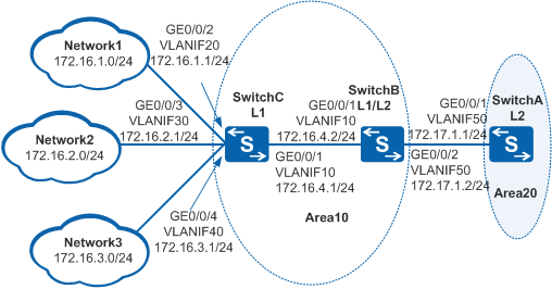
As shown in Figure 1, three switches run IS-IS to communicate with each other. SwitchA is a Level-2 device, SwitchB is a Level-1-2 device, and SwitchC is a Level-1 device. SwitchA is heavily loaded because there are too many routing entries on the IS-IS network. Therefore, system resource consumption of SwitchA needs to be reduced.
Configuration Roadmap
The configuration roadmap is as follows:
Configure IP addresses for interfaces and enable IS-IS on each switch so that the switches can be interconnected.
Configure route summarization on SwitchB to reduce the routing table size of SwitchA without affecting data forwarding so that the system resource consumption of SwitchA can be reduced.
Procedure
- Create VLANs and add corresponding interfaces to the VLANs.
# Configure SwitchA. The configurations of SwitchB and SwitchC are similar to the configuration of SwitchA.
<HUAWEI> system-view
[HUAWEI] sysname SwitchA
[SwitchA] vlan batch 50
[SwitchA] interface gigabitethernet 0/0/1
[SwitchA-GigabitEthernet0/0/1] port link-type trunk
[SwitchA-GigabitEthernet0/0/1] port trunk allow-pass vlan 50
[SwitchA-GigabitEthernet0/0/1] quit
- Assign an IP address to each VLANIF interface.
# Configure SwitchA. The configurations of SwitchB and SwitchC are similar to the configuration of SwitchA.
[SwitchA] interface vlanif 50
[SwitchA-Vlanif50] ip address 172.17.1.1 24
[SwitchA-Vlanif50] quit
- Configure basic IS-IS functions.
# Configure SwitchA.
[SwitchA] isis 1
[SwitchA-isis-1] is-level level-2
[SwitchA-isis-1] network-entity 20.0000.0000.0001.00
[SwitchA-isis-1] quit
[SwitchA] interface vlanif 50
[SwitchA-Vlanif50] isis enable 1
[SwitchA-Vlanif50] quit
# Configure SwitchB.
[SwitchB] isis 1
[SwitchB-isis-1] network-entity 10.0000.0000.0002.00
[SwitchB-isis-1] quit
[SwitchB] interface vlanif 10
[SwitchB-Vlanif10] isis enable 1
[SwitchB-Vlanif10] quit
[SwitchB] interface vlanif 50
[SwitchB-Vlanif50] isis enable 1
[SwitchB-Vlanif50] quit
# Configure SwitchC.
[SwitchC] isis 1
[SwitchC-isis-1] is-level level-1
[SwitchC-isis-1] network-entity 10.0000.0000.0003.00
[SwitchC-isis-1] quit
[SwitchC] interface vlanif 10
[SwitchC-Vlanif10] isis enable 1
[SwitchC-Vlanif10] quit
[SwitchC] interface vlanif 20
[SwitchC-Vlanif20] isis enable 1
[SwitchC-Vlanif20] quit
[SwitchC] interface vlanif 30
[SwitchC-Vlanif30] isis enable 1
[SwitchC-Vlanif30] quit
[SwitchC] interface vlanif 40
[SwitchC-Vlanif40] isis enable 1
[SwitchC-Vlanif40] quit
- Check the IS-IS routing table of SwitchA.
[SwitchA]display isis route

                         Route information for ISIS(1)
                         -----------------------------

                        ISIS(1) Level-2 Forwarding Table
                        --------------------------------

 IPV4 Destination     IntCost    ExtCost ExitInterface   NextHop         Flags
-------------------------------------------------------------------------------
 172.17.1.0/24        10         NULL    Vlanif50        Direct          D/-/L/-
 172.16.1.0/24        30         NULL    Vlanif50        172.17.1.2      A/-/-/-
 172.16.2.0/24        30         NULL    Vlanif50        172.17.1.2      A/-/-/-
 172.16.3.0/24        30         NULL    Vlanif50        172.17.1.2      A/-/-/-
 172.16.4.0/24        20         NULL    Vlanif50        172.17.1.2      A/-/-/-
     Flags: D-Direct, A-Added to URT, L-Advertised in LSPs, S-IGP Shortcut,
                               U-Up/Down Bit Set
- Configure route summarization on SwitchB.
# Summarize 172.16.1.0/24, 172.16.2.0/24, 172.16.3.0/24, and 172.16.4.0/24 as 172.16.0.0/16 on SwitchB.
[SwitchB] isis 1
[SwitchB-isis-1] summary 172.16.0.0 255.255.0.0 level-1-2
[SwitchB-isis-1] quit
- Verify the configuration.
# Check the IS-IS routing table of SwitchA. The routing table contains the route 172.16.0.0/16 summarized from 172.16.1.0/24, 172.16.2.0/24, 172.16.3.0/24, and 172.16.4.0/24.
[SwitchA] display isis route

                         Route information for ISIS(1)
                         -----------------------------

                        ISIS(1) Level-2 Forwarding Table
                        --------------------------------

 IPV4 Destination     IntCost    ExtCost ExitInterface   NextHop         Flags
-------------------------------------------------------------------------------
 172.17.1.0/24        10         NULL    Vlanif50        Direct          D/-/L/-
 172.16.0.0/16        20         NULL    Vlanif50        172.17.1.2      A/-/-/-
     Flags: D-Direct, A-Added to URT, L-Advertised in LSPs, S-IGP Shortcut,
                               U-Up/Down Bit Set
Configuration Files
SwitchA configuration file
#
sysname SwitchA
#
vlan batch 50
#
isis 1
 is-level level-2
 network-entity 20.0000.0000.0001.00
#
interface Vlanif50
 ip address 172.17.1.1 255.255.255.0
 isis enable 1
#
interface GigabitEthernet0/0/1
 port link-type trunk
 port trunk allow-pass vlan 50
#
return
SwitchB configuration file
#
sysname SwitchB
#
vlan batch 10 50
#
isis 1
 network-entity 10.0000.0000.0002.00
 summary 172.16.0.0 255.255.0.0 level-1-2
#
interface Vlanif10
 ip address 172.16.4.2 255.255.255.0
 isis enable 1
#
interface Vlanif50
 ip address 172.17.1.2 255.255.255.0
 isis enable 1
#
interface GigabitEthernet0/0/1
 port link-type trunk
 port trunk allow-pass vlan 10
#
interface GigabitEthernet0/0/2
 port link-type trunk
 port trunk allow-pass vlan 50
#
return
SwitchC configuration file
#
sysname SwitchC
#
vlan batch 10 20 30 40
#
isis 1
 is-level level-1
 network-entity 10.0000.0000.0003.00
#
interface Vlanif10
 ip address 172.16.4.1 255.255.255.0
 isis enable 1
#
interface Vlanif20
 ip address 172.16.1.1 255.255.255.0
 isis enable 1
#
interface Vlanif30
 ip address 172.16.2.1 255.255.255.0
 isis enable 1
#
interface Vlanif40
 ip address 172.16.3.1 255.255.255.0
 isis enable 1
#
interface GigabitEthernet0/0/1
 port link-type trunk
 port trunk allow-pass vlan 10
#
interface GigabitEthernet0/0/2
 port link-type trunk
 port trunk allow-pass vlan 20
#
interface GigabitEthernet0/0/3
 port link-type trunk
 port trunk allow-pass vlan 30
#
interface GigabitEthernet0/0/4
 port link-type trunk
 port trunk allow-pass vlan 40
#
return
