Example for Configuring IS-IS GR
Networking Requirements
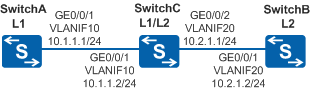
As shown in Figure 1, SwitchA, SwitchB, and SwitchC belong to the same autonomous system. They run IS-IS to implement interworking and provide the GR mechanism. When IS-IS is restarted on SwitchA, SwitchA resends connection requests to neighbors to synchronize the LSDB.
Configuration Roadmap
- Enable IS-IS on each Switch so that the Switches can be interconnected.
- Configure GR in the IS-IS view on each Switch and configure the same interval for the restart.
Procedure
- Configure VLANs that the related interfaces belong to.
# Configure SwitchA. The configurations of SwitchB and SwitchC are similar to the configuration of SwitchA.
<HUAWEI> system-view
[HUAWEI] sysname SwitchA
[SwitchA] vlan 10
[SwitchA-vlan10] quit
[SwitchA] interface gigabitethernet 0/0/1
[SwitchA-GigabitEthernet0/0/1] port link-type trunk
[SwitchA-GigabitEthernet0/0/1] port trunk allow-pass vlan 10
[SwitchA-GigabitEthernet0/0/1] quit
- Assign an IP address to each VLANIF interface.
# Configure SwitchA. The configurations of SwitchB and SwitchC are similar to the configuration of SwitchA.
[SwitchA] interface vlanif10
[SwitchA-Vlanif10] ip address 10.1.1.1 24
[SwitchA-Vlanif10] quit
- Configure basic IS-IS functions.
# Configure SwitchA.
[SwitchA] isis 1
[SwitchA-isis-1] is-level level-1
[SwitchA-isis-1] network-entity 10.0000.0000.0001.00
[SwitchA-isis-1] quit
[SwitchA] interface vlanif 10
[SwitchA-Vlanif10] isis enable 1
[SwitchA-Vlanif10] quit
# Configure SwitchB.
[SwitchB] isis 1
[SwitchB-isis-1] is-level level-2
[SwitchB-isis-1] network-entity 10.0000.0000.0002.00
[SwitchB-isis-1] quit
[SwitchB] interface vlanif 20
[SwitchB-Vlanif20] isis enable 1
[SwitchB-Vlanif20] quit
# Configure SwitchC.
[SwitchC] isis 1
[SwitchC-isis-1] network-entity 10.0000.0000.0003.00
[SwitchC-isis-1] quit
[SwitchC] interface vlanif 10
[SwitchC-Vlanif10] isis enable 1
[SwitchC-Vlanif10] quit
[SwitchC] interface vlanif 20
[SwitchC-Vlanif20] isis enable 1
[SwitchC-Vlanif20] quit
- Configure IS-IS GR and set the restart interval.
# Configure SwitchA. The configurations of SwitchB and SwitchC are similar to the configuration of SwitchA.
[SwitchA] isis 1
[SwitchA-isis-1] graceful-restart
[SwitchA-isis-1] graceful-restart interval 150
[SwitchA-isis-1] quit
[SwitchA] quit
- Verify the configuration.
# Run the display fib command on SwitchA to view the Forwarding Information Base (FIB) table.
<SwitchA> display fib
Route Flags: G - Gateway Route, H - Host Route,    U - Up Route
             S - Static Route,  D - Dynamic Route, B - Black Hole Route
             L - Vlink Route
--------------------------------------------------------------------------------
FIB Table:
 Total number of Routes : 5

Destination/Mask  Nexthop         Flag TimeStamp     Interface       TunnelID
127.0.0.1/32      127.0.0.1       HU   t[21]         InLoop0         0x0
127.0.0.0/8       127.0.0.1       U    t[21]         InLoop0         0x0
10.1.1.1/32       127.0.0.1       HU   t[20678]      InLoop0         0x0
10.1.1.0/24       10.1.1.1        U    t[20678]      Vlanif10        0x0
10.2.1.0/24       10.1.1.2        DGU  t[79388]      Vlanif10        0x0
# Reset the IS-IS process by using the GR method on SwitchA.
<SwitchA> reset isis all graceful-restart
The Switch restarts an IS-IS process in GR mode only when GR is enabled for the IS-IS process.
# Run the display fib command on SwitchA and view the FIB table to check whether GR works normally. If GR works normally, the FIB table does not change and the forwarding service is not affected when SwitchA restarts the IS-IS process in GR mode.
<SwitchA> display fib
Route Flags: G - Gateway Route, H - Host Route,    U - Up Route
             S - Static Route,  D - Dynamic Route, B - Black Hole Route
             L - Vlink Route
--------------------------------------------------------------------------------
FIB Table:
 Total number of Routes : 5

Destination/Mask  Nexthop         Flag TimeStamp     Interface       TunnelID
127.0.0.1/32      127.0.0.1       HU   t[21]         InLoop0         0x0
127.0.0.0/8       127.0.0.1       U    t[21]         InLoop0         0x0
10.1.1.1/32       127.0.0.1       HU   t[20678]      InLoop0         0x0
10.1.1.0/24       10.1.1.1        U    t[20678]      Vlanif10        0x0
10.2.1.0/24       10.1.1.2        DGU  t[79388]      Vlanif10        0x0
As shown in the display, the FIB table on SwitchA does not change and the forwarding service is not affected.
# Disable IS-IS GR on SwitchA.
<SwitchA> system-view
[SwitchA] isis 1
[SwitchA-isis-1] undo graceful-restart
[SwitchA-isis-1] quit
[SwitchA] quit
# Reset the IS-IS process on SwitchA.
<SwitchA> reset isis all# Run the display fib command on SwitchA to view the FIB table.
<SwitchA> display fib
Route Flags: G - Gateway Route, H - Host Route,    U - Up Route
             S - Static Route,  D - Dynamic Route, B - Black Hole Route
             L - Vlink Route
--------------------------------------------------------------------------------
FIB Table:
 Total number of Routes : 4

Destination/Mask  Nexthop         Flag TimeStamp     Interface       TunnelID
127.0.0.1/32      127.0.0.1       HU   t[21]         InLoop0         0x0
127.0.0.0/8       127.0.0.1       U    t[21]         InLoop0         0x0
10.1.1.1/32       127.0.0.1       HU   t[20678]      InLoop0         0x0
10.1.1.0/24       10.1.1.1        U    t[20678]      Vlanif10        0x0
As shown in the display, the FIB table on SwitchA changes and the forwarding service is affected.
Configuration Files
SwitchA configuration file
#
sysname SwitchA
#
vlan batch 10
#
isis 1
 graceful-restart
 graceful-restart interval 150
 is-level level-1
 network-entity 10.0000.0000.0001.00
#
interface Vlanif10
 ip address 10.1.1.1 255.255.255.0
 isis enable 1
#
interface GigabitEthernet0/0/1
 port link-type trunk
 port trunk allow-pass vlan 10
#
return
SwitchB configuration file
#
sysname SwitchB
#
vlan batch 20
#
isis 1
 graceful-restart
 graceful-restart interval 150
 is-level level-2
 network-entity 10.0000.0000.0002.00
#
interface Vlanif20
 ip address 10.2.1.2 255.255.255.0
 isis enable 1
#
interface GigabitEthernet0/0/1
 port link-type trunk
 port trunk allow-pass vlan 20
#
return
SwitchC configuration file
#
sysname SwitchC
#
vlan batch 10 20
#
isis 1
 graceful-restart
 graceful-restart interval 150
 network-entity 10.0000.0000.0003.00
#
interface Vlanif10
 ip address 10.1.1.2 255.255.255.0
 isis enable 1
#
interface Vlanif20
 ip address 10.2.1.1 255.255.255.0
 isis enable 1
#
interface GigabitEthernet0/0/1
 port link-type trunk
 port trunk allow-pass vlan 10
#
interface GigabitEthernet0/0/2
 port link-type trunk
 port trunk allow-pass vlan 20
#
return