Example for Configuring Dynamic BFD for IS-IS
Networking Requirements
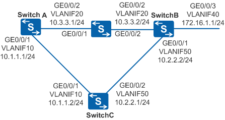
As shown in Figure 1, three routers are interconnected using IS-IS, and SwitchA and SwitchB communicate with each other through a Layer 2 switch. When the link that passes through the switch between SwitchA and SwitchB fails, the two routers need to rapidly respond to the fault, and traffic can be switched to the link that passes through SwitchC for forwarding.

In this scenario, ensure that all connected interfaces have STP disabled. If STP is enabled and VLANIF interfaces of switches are used to construct a Layer 3 ring network, an interface on the network will be blocked. As a result, Layer 3 services on the network cannot run normally.
Configuration Roadmap
The configuration roadmap is as follows:
Configure IP addresses for interfaces and enable IS-IS on each router to ensure reachable routes between the routers.
Set the IS-IS interface cost to control route selection of the routers to make the link that passes through the switch from SwitchA to SwitchB as the primary link and the link that passes through SwitchC as the backup link.
Configure dynamic BFD for IS-IS on SwitchA, SwitchB, and SwitchC so that link faults can be detected rapidly and traffic can be switched to the backup link for forwarding.
Procedure
- Configure VLANs that each interface belongs to.
# Configure SwitchA. The configurations of SwitchB and SwitchC are similar to the configuration of SwitchA.
<HUAWEI> system-view
[HUAWEI] sysname SwitchA
[SwitchA] vlan batch 10 20
[SwitchA] interface gigabitethernet 0/0/1
[SwitchA-GigabitEthernet0/0/1] port link-type trunk
[SwitchA-GigabitEthernet0/0/1] port trunk allow-pass vlan 10
[SwitchA-GigabitEthernet0/0/1] quit
[SwitchA] interface gigabitethernet 0/0/2
[SwitchA-GigabitEthernet0/0/2] port link-type trunk
[SwitchA-GigabitEthernet0/0/2] port trunk allow-pass vlan 20
[SwitchA-GigabitEthernet0/0/2] quit
- Assign the IP addresses for VLANIF interfaces.
# Configure SwitchA. The configurations of SwitchB and SwitchC are similar to the configuration of SwitchA.
[SwitchA] interface vlanif 10
[SwitchA-Vlanif10] ip address 10.1.1.1 24
[SwitchA-Vlanif10] quit
[SwitchA] interface vlanif 20
[SwitchA-Vlanif20] ip address 10.3.3.1 24
[SwitchA-Vlanif20] quit
- Configure basic IS-IS functions.
# Configure SwitchA.
[SwitchA] isis
[SwitchA-isis-1] is-level level-2
[SwitchA-isis-1] network-entity 10.0000.0000.0001.00
[SwitchA-isis-1] quit
[SwitchA] interface vlanif10
[SwitchA-Vlanif10] isis enable 1
[SwitchA-Vlanif10] quit
[SwitchA] interface vlanif 20
[SwitchA-Vlanif20] isis enable 1
[SwitchA-Vlanif20] quit
# Configure SwitchB.
[SwitchB] isis
[SwitchB-isis-1] is-level level-2
[SwitchB-isis-1] network-entity 10.0000.0000.0002.00
[SwitchB-isis-1] quit
[SwitchB] interface vlanif 50
[SwitchB-Vlanif50] isis enable 1
[SwitchB-Vlanif50] quit
[SwitchB] interface vlanif 20
[SwitchB-Vlanif20] isis enable 1
[SwitchB-Vlanif20] quit
[SwitchB] interface vlanif 40
[SwitchB-Vlanif40] isis enable 1
[SwitchB-Vlanif40] quit
# Configure SwitchC.
[SwitchC] isis
[SwitchC-isis-1] is-level level-2
[SwitchC-isis-1] network-entity 10.0000.0000.0003.00
[SwitchC-isis-1] quit
[SwitchC] interface vlanif 10
[SwitchC-Vlanif10] isis enable 1
[SwitchC-Vlanif10] quit
[SwitchC] interface vlanif 50
[SwitchC-Vlanif50] isis enable 1
[SwitchC-Vlanif50] quit
# After the preceding configurations, run the display isis peer command. You can see that the neighbor relationships are established between SwitchA and SwitchB, and between SwitchA and SwitchC. The following uses the configuration of SwitchA as an example.
[SwitchA] display isis peer

                          Peer information for ISIS(1)

  System Id     Interface          Circuit Id       State HoldTime Type     PRI
-------------------------------------------------------------------------------
0000.0000.0003  Vlanif10          0000.0000.0001.02 Up    21s      L2       64
0000.0000.0002  Vlanif20          0000.0000.0002.01 Up    9s       L2       64

Total Peer(s): 2
# Switches have learned routes from each other. The following uses the routing table of SwitchA as an example.
[SwitchA] display ip routing-table
Route Flags: R - relay, D - download to fib, T - to vpn-instance
------------------------------------------------------------------------------
Routing Tables: Public
         Destinations : 8        Routes : 9

Destination/Mask    Proto   Pre  Cost     Flags NextHop         Interface

       10.1.1.0/24  Direct  0    0          D   10.1.1.1        Vlanif10
       10.1.1.1/32  Direct  0    0          D   127.0.0.1       Vlanif10
       10.2.2.0/24  ISIS-L2 15   20         D   10.3.3.2        Vlanif20
                    ISIS-L2 15   20         D   10.1.1.2        Vlanif10
       10.3.3.0/24  Direct  0    0          D   10.3.3.1        Vlanif20
       10.3.3.1/32  Direct  0    0          D   127.0.0.1       Vlanif20
      127.0.0.0/8   Direct  0    0          D   127.0.0.1       InLoopBack0
      127.0.0.1/32  Direct  0    0          D   127.0.0.1       InLoopBack0
     172.16.1.0/24  ISIS-L2 15   20         D   10.3.3.2        Vlanif20
As shown in the routing table, the next-hop address of the route to 172.16.1.0/24 is 10.3.3.2, and traffic is transmitted on the primary link SwitchA→SwitchB.
- Set the interface cost.
# Configure SwitchA.
[SwitchA]  interface vlanif 20
[SwitchA-Vlanif20] isis cost 5
[SwitchA-Vlanif20] quit
# Configure SwitchB.
[SwitchB]  interface vlanif 20
[SwitchB-Vlanif20] isis cost 5
[SwitchB-Vlanif20] quit
- Configure BFD for IS-IS processes.
# Enable BFD for IS-IS on SwitchA.
[SwitchA] bfd
[SwitchA-bfd] quit
[SwitchA] isis
[SwitchA-isis-1] bfd all-interfaces enable
[SwitchA-isis-1] quit
# Enable BFD for IS-IS on SwitchB.
[SwitchB] bfd
[SwitchB-bfd] quit
[SwitchB] isis
[SwitchB-isis-1] bfd all-interfaces enable
[SwitchB-isis-1] quit
# Enable BFD for IS-IS on SwitchC.
[SwitchC] bfd
[SwitchC-bfd] quit
[SwitchC] isis
[SwitchC-isis-1] bfd all-interfaces enable
[SwitchC-isis-1] quit
# After the preceding configurations, run the display isis bfd session all command on SwitchA, SwitchB, and SwitchC. You can see that the BFD session status is Up.
The following uses the display on SwitchA as an example.
[SwitchA] display isis bfd session all

                      BFD session information for ISIS(1)
                      -----------------------------------

Peer System ID : 0000.0000.0003        Interface : Vlanif10
TX : 1000          BFD State : up      Peer IP Address : 10.1.1.2
RX : 1000          LocDis : 8193       Local IP Address: 10.1.1.1
Multiplier : 3     RemDis : 8193       Type : L2
Diag : No diagnostic information

Peer System ID : 0000.0000.0002        Interface : Vlanif20
TX : 1000          BFD State : up      Peer IP Address : 10.3.3.2
RX : 1000          LocDis : 8192       Local IP Address: 10.3.3.1
Multiplier : 3     RemDis : 8192       Type : L2
Diag : No diagnostic information

Total BFD session(s): 2
As shown in the preceding display, the status of the BFD session between SwitchA and SwitchB and that between SwitchA and SwitchC is Up.
- Configure BFD for IS-IS interfaces.
# Configure BFD on VLANIF20 of SwitchA, set the minimum interval for sending packets to 100 ms, the minimum interval for receiving packets to 100 ms, and the local detection multiplier to 4.
[SwitchA]  interface vlanif 20
[SwitchA-Vlanif20] isis bfd enable
[SwitchA-Vlanif20] isis bfd min-tx-interval 100 min-rx-interval 100 detect-multiplier 4
[SwitchA-Vlanif20] quit
# Configure BFD on VLANIF20 of SwitchB, set the minimum interval for sending packets to 100 ms, the minimum interval for receiving packets to 100 ms, and the local detection multiplier to 4.
[SwitchB]  interface vlanif 20
[SwitchB-Vlanif20] isis bfd enable
[SwitchB-Vlanif20] isis bfd min-tx-interval 100 min-rx-interval 100 detect-multiplier 4
[SwitchB-Vlanif20] quit
# After the preceding configurations, run the display isis bfd session all command on SwitchA or SwitchB. You can see that the BFD parameters have taken effect. The following uses the display on SwitchB as an example.
[SwitchB] display isis bfd session all BFD session information for ISIS(1) ----------------------------------- Peer System ID : 0000.0000.0003 Interface : Vlanif50 TX : 1000 BFD State : up Peer IP Address : 10.2.2.1 RX : 1000 LocDis : 8192 Local IP Address: 10.2.2.2 Multiplier : 3 RemDis : 8193 Type : L2 Diag : No diagnostic information Peer System ID : 0000.0000.0001 Interface : Vlanif20 TX : 100 BFD State : up Peer IP Address : 10.3.3.1 RX : 100 LocDis : 8192 Local IP Address: 10.3.3.2 Multiplier : 4 RemDis : 8192 Type : L2 Diag : No diagnostic information Total BFD session(s): 2 - Verify the configuration.
# Run the shutdown command on GigabitEthernet0/0/2 of SwitchB to simulate a primary link failure.
[SwitchB] interface gigabitethernet 0/0/2
[SwitchB-GigabitEthernet0/0/2] shutdown
- # View the routing table of SwitchA.
[SwitchA] display ip routing-table
Route Flags: R - relay, D - download to fib, T - to vpn-instance
------------------------------------------------------------------------------
Routing Tables: Public
         Destinations : 8        Routes : 8

Destination/Mask    Proto       Pre  Cost     Flags NextHop         Interface

       10.1.1.0/24  Direct      0    0          D   10.1.1.1        Vlanif10
       10.1.1.1/32  Direct      0    0          D   127.0.0.1       Vlanif10
       10.2.2.0/24  ISIS-L2     15   20         D   10.1.1.2        Vlanif10
       10.3.3.0/24  Direct  0    0          D   10.3.3.1        Vlanif20
       10.3.3.1/32  Direct  0    0          D   127.0.0.1       Vlanif20
      127.0.0.0/8   Direct      0    0          D   127.0.0.1       InLoopBack0
      127.0.0.1/32  Direct      0    0          D   127.0.0.1       InLoopBack0
     172.16.1.0/24  ISIS-L2     15   30         D   10.1.1.2        Vlanif10
As shown in the routing table, the backup link SwitchA→SwitchC→SwitchB takes effect after the primary link fails, and the next-hop address of the route to 172.16.1.0/24 becomes 10.1.1.2.
# Run the display isis bfd session all command on SwitchA. You can see that the status of the BFD session between SwitchA and SwitchC is Up.
[SwitchA] display isis bfd session all

                      BFD session information for ISIS(1)
                      -----------------------------------

Peer System ID : 0000.0000.0003        Interface : Vlanif10
TX : 1000          BFD State : up      Peer IP Address : 10.1.1.2
RX : 1000          LocDis : 8193       Local IP Address: 10.1.1.1
Multiplier : 3     RemDis : 8193       Type : L2
Diag : No diagnostic information

Total BFD session(s): 1
Configuration Files
Switch configuration file
#
sysname Switch
#
vlan batch 20
#
interface GigabitEthernet0/0/1
 port link-type trunk
 port trunk allow-pass vlan 20
#
interface GigabitEthernet0/0/2
 port link-type trunk
 port trunk allow-pass vlan 20
#
return
SwitchA configuration file
#
sysname SwitchA
#
vlan batch 10 20
#
bfd
#
isis 1
 is-level level-2
 bfd all-interfaces enable
 network-entity 10.0000.0000.0001.00
#
interface Vlanif10
 ip address 10.1.1.1 255.255.255.0
 isis enable 1
#
interface Vlanif20
 ip address 10.3.3.1 255.255.255.0
 isis enable 1
 isis cost 5
 isis bfd enable
 isis bfd min-tx-interval 100 min-rx-interval 100 detect-multiplier 4
#
interface GigabitEthernet0/0/1
 port link-type trunk
 port trunk allow-pass vlan 10
#
interface GigabitEthernet0/0/2
 port link-type trunk
 port trunk allow-pass vlan 20
#
return
SwitchB configuration file
#
sysname SwitchB
#
vlan batch 20 40 50
#
bfd
#
isis 1
 is-level level-2
 bfd all-interfaces enable
 network-entity 10.0000.0000.0002.00
#
interface Vlanif20
 ip address 10.3.3.2 255.255.255.0
 isis enable 1
 isis cost 5
 isis bfd enable
 isis bfd min-tx-interval 100 min-rx-interval 100 detect-multiplier 4
#
interface Vlanif40
 ip address 172.16.1.1 255.255.255.0
 isis enable 1
#
interface Vlanif50
 ip address 10.2.2.2 255.255.255.0
 isis enable 1
#
interface GigabitEthernet0/0/1
 port link-type trunk
 port trunk allow-pass vlan 50
#
interface GigabitEthernet0/0/2
 port link-type trunk
 port trunk allow-pass vlan 20
#
interface GigabitEthernet0/0/3
 port link-type trunk
 port trunk allow-pass vlan 40
#
return
SwitchC configuration file
#
sysname SwitchC
#
vlan batch 10 50
#
bfd
#
isis 1
 is-level level-2
 bfd all-interfaces enable
 network-entity 10.0000.0000.0003.00
#
interface Vlanif10
 ip address 10.1.1.2 255.255.255.0
 isis enable 1
#
interface Vlanif50
 ip address 10.2.2.1 255.255.255.0
 isis enable 1
#
interface GigabitEthernet0/0/1
 port link-type trunk
 port trunk allow-pass vlan 10
#
interface GigabitEthernet0/0/2
 port link-type trunk
 port trunk allow-pass vlan 50
#
return