Example for Configuring Dynamic BFD for IPv6 IS-IS
Networking Requirements
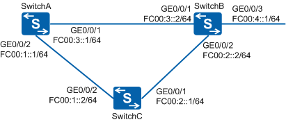
In Figure 1, IS-IS is run among SwitchA, SwitchB, and SwitchC. Service traffic is forwarded along the primary link SwitchA→SwitchB. The link SwitchA→SwitchC→SwitchB is used as a backup. Customers require that a fault on the primary link be detected in milliseconds so that service traffic can be fast switched to the backup link if the primary link fails.

In this scenario, ensure that all connected interfaces have STP disabled. If STP is enabled and VLANIF interfaces of switches are used to construct a Layer 3 ring network, an interface on the network will be blocked. As a result, Layer 3 services on the network cannot run normally.
Configuration Roadmap
The configuration roadmap is as follows:
Configure basic IS-IS IPv6 functions on each switch.
Set link cost values for IS-IS interfaces on each switch to make the path SwitchA→SwitchB become the primary and the path SwitchA→SwitchC→SwitchB become the backup.
Enable BFD globally on each switch to detect faults on the primary link in milliseconds.
Enable IPv6 BFD for IS-IS in the IS-IS view on each switch so that service traffic can be fast switched to the backup link when the primary link fails.
Procedure
- Enable the IPv6 forwarding capability and configure IPv6
addresses for interfaces.
# Configure SwitchA. Ensure that the configurations of SwitchB and SwitchC are the same as the configuration of SwitchA.
<HUAWEI> system-view
[HUAWEI] sysname SwitchA
[SwitchA] ipv6
[SwitchA] interface GigabitEthernet 0/0/1
[SwitchA-GigabitEthernet0/0/1] undo portswitch
[SwitchA-GigabitEthernet0/0/1] ipv6 enable
[SwitchA-GigabitEthernet0/0/1] ipv6 address FC00:3::1 64
[SwitchA-GigabitEthernet0/0/1] quit
[SwitchA] interface GigabitEthernet 0/0/2
[SwitchA-GigabitEthernet0/0/2] undo portswitch
[SwitchA-GigabitEthernet0/0/2] ipv6 enable
[SwitchA-GigabitEthernet0/0/2] ipv6 address FC00:1::1 64
[SwitchA-GigabitEthernet0/0/2] quit
- Configure basic IS-IS IPv6 functions.
# Configure SwitchA.
[SwitchA] isis 10
[SwitchA-isis-10] is-level level-2
[SwitchA-isis-10] network-entity 10.0000.0000.0001.00
[SwitchA-isis-10] ipv6 enable
[SwitchA-isis-10] quit
[SwitchA] interface GigabitEthernet 0/0/1
[SwitchA-GigabitEthernet0/0/1] isis ipv6 enable 10
[SwitchA-GigabitEthernet0/0/1] quit
[SwitchA] interface GigabitEthernet 0/0/2
[SwitchA-GigabitEthernet0/0/2] isis ipv6 enable 10
[SwitchA-GigabitEthernet0/0/2] quit
# Configure SwitchB.
[SwitchB] isis 10
[SwitchB-isis-10] is-level level-2
[SwitchB-isis-10] network-entity 10.0000.0000.0003.00
[SwitchB-isis-10] ipv6 enable
[SwitchB-isis-10] quit
[SwitchB] interface GigabitEthernet 0/0/1
[SwitchB-GigabitEthernet0/0/1] isis ipv6 enable 10
[SwitchB-GigabitEthernet0/0/1] quit
[SwitchB] interface GigabitEthernet 0/0/2
[SwitchB-GigabitEthernet0/0/2] isis ipv6 enable 10
[SwitchB-GigabitEthernet0/0/2] quit
[SwitchB] interface GigabitEthernet 0/0/3
[SwitchB-GigabitEthernet0/0/3] isis ipv6 enable 10
[SwitchB-GigabitEthernet0/0/3] quit
# Configure SwitchC.
[SwitchC] isis 10
[SwitchC-isis-10] is-level level-2
[SwitchC-isis-10] network-entity 10.0000.0000.0002.00
[SwitchC-isis-10] ipv6 enable
[SwitchC-isis-10] quit
[SwitchC] interface GigabitEthernet 0/0/1
[SwitchC-GigabitEthernet0/0/1] isis ipv6 enable 10
[SwitchC-GigabitEthernet0/0/1] quit
[SwitchC] interface GigabitEthernet 0/0/2
[SwitchC-GigabitEthernet0/0/2] isis ipv6 enable 10
[SwitchC-GigabitEthernet0/0/2] quit
# After the configurations are complete, run the display ipv6 routing-table command. You can view that the switches have learnt IPv6 routes from each other.
- Set link cost values for IS-IS interfaces.
# Configure SwitchA.
[SwitchA] interface GigabitEthernet 0/0/1
[SwitchA-GigabitEthernet0/0/1] isis cost 1 level-2
[SwitchA-GigabitEthernet0/0/1] quit
[SwitchA] interface GigabitEthernet 0/0/2
[SwitchA-GigabitEthernet0/0/2] isis cost 10 level-2
[SwitchA-GigabitEthernet0/0/2] quit
# Configure SwitchB.
[SwitchB] interface GigabitEthernet 0/0/1
[SwitchB-GigabitEthernet0/0/1] isis cost 1 level-2
[SwitchB-GigabitEthernet0/0/1] quit
[SwitchB] interface GigabitEthernet 0/0/2
[SwitchB-GigabitEthernet0/0/2] isis cost 10 level-2
[SwitchB-GigabitEthernet0/0/2] quit
[SwitchB] interface GigabitEthernet 0/0/3
[SwitchB-GigabitEthernet0/0/3] isis cost 10 level-2
[SwitchB-GigabitEthernet0/0/3] quit
# Configure SwitchC.
[SwitchC] interface GigabitEthernet 0/0/1
[SwitchC-GigabitEthernet0/0/1] isis cost 10 level-2
[SwitchC-GigabitEthernet0/0/1] quit
[SwitchC] interface GigabitEthernet 0/0/2
[SwitchC-GigabitEthernet0/0/2] isis cost 10 level-2
[SwitchC-GigabitEthernet0/0/2] quit
- Configure IPv6 BFD for IS-IS.
# Enable IPv6 BFD for IS-IS globally on SwitchA, SwitchB, and SwitchC, and set the minimum intervals for sending and receiving BFD packets to 150 milliseconds.
# Configure SwitchA.
[SwitchA] bfd
[SwitchA-bfd] quit
[SwitchA] isis 10
[SwitchA-isis-10] ipv6 bfd all-interfaces enable
[SwitchA-isis-10] ipv6 bfd all-interfaces min-tx-interval 150 min-rx-interval 150
[SwitchA-isis-10] quit
# Configure SwitchB.
[SwitchB] bfd
[SwitchB-bfd] quit
[SwitchB] isis 10
[SwitchB-isis-10] ipv6 bfd all-interfaces enable
[SwitchB-isis-10] ipv6 bfd all-interfaces min-tx-interval 150 min-rx-interval 150
[SwitchB-isis-10] quit
# Configure SwitchC.
[SwitchC] bfd
[SwitchC-bfd] quit
[SwitchC] isis 10
[SwitchC-isis-10] ipv6 bfd all-interfaces enable
[SwitchC-isis-10] ipv6 bfd all-interfaces min-tx-interval 150 min-rx-interval 150
[SwitchC-isis-10] quit
# After the configurations are complete, run the display isis ipv6 bfd session all command on SwitchA or SwitchB. You can view that IPv6 BFD parameters already take effect. Take the display on SwitchA as an example:
[SwitchA] display isis ipv6 bfd session all IPv6 BFD session information for ISIS(10) ----------------------------------------- Peer System ID : 0000.0000.0003 Type : L2 Interface : GE0/0/1 IPv6 BFD State : up TX : 150 RX : 150 Multiplier : 3 LocDis : 8198 Local IPv6 Address : FE80::200:13FF:FE82:4569 RemDis : 8199 Peer IPv6 Address : FE80::201:FF:FE01:1 Diag : No diagnostic information Peer System ID : 0000.0000.0002 Type : L2 Interface : GE0/0/2 IPv6 BFD State : up TX : 150 RX : 150 Multiplier : 3 LocDis : 8197 Local IPv6 Address : FE80::200:13FF:FE82:4569 RemDis : 8199 Peer IPv6 Address : FE80::225:9EFF:FEFB:BFF1 Diag : No diagnostic information Total IPv6 BFD session(s): 2 - Verify the configuration.
# On SwitchA, run the display ipv6 routing-table FC00:4::1 64 command to view the IPv6 routing table. You can view that the next hop address of the route to FC00:4::/64 is FE80::201:FF:FE01:1 and the outbound interface is GE0/0/1.
[SwitchA] display ipv6 routing-table FC00:4::1 64
Routing Table :Public
Summary Count : 1

 Destination  : FC00:4::                        PrefixLength : 64
 NextHop      : FE80::201:FF:FE01:1             Preference   : 15
 Cost         : 11                              Protocol     : ISIS-L2
 RelayNextHop : ::                              TunnelID     : 0x0
 Interface    : GigabitEthernet0/0/1            Flags        : D
# Run the shutdown command on GE0/0/1 of SwitchB to simulate a primary link fault.
[SwitchB] interface GigabitEthernet 0/0/1
[SwitchB-GigabitEthernet0/0/1] shutdown
# On SwitchA, run the display ipv6 routing-table FC00:4::1 64 command to view the IPv6 routing table.
[SwitchA] display ipv6 routing-table FC00:4::1 64
Routing Table :Public
Summary Count : 1

 Destination  : FC00:4::                        PrefixLength : 64
 NextHop      : FE80::225:9EFF:FEFB:BFF1        Preference   : 15
 Cost         : 30                              Protocol     : ISIS-L2
 RelayNextHop : ::                              TunnelID     : 0x0
 Interface    : GigabitEthernet0/0/2            Flags        : D
In the IPv6 routing table, you can view that the backup link transmits traffic after the primary link fails, the next hop address of the route to FC00:4::/64 becomes FE80::225:9EFF:FEFB:BFF1, and the outbound interface becomes GE0/0/2.
# Run the display isis ipv6 bfd session all command on SwitchA, and you can view that only one BFD session is established between SwitchA and SwitchC and its status is Up.
[SwitchA] display isis ipv6 bfd session all

                   IPv6 BFD session information for ISIS(10)
                   -----------------------------------------

Peer System ID : 0000.0000.0002   Type : L2
Interface : GE0/0/2
IPv6 BFD State : up       TX : 150   RX : 150   Multiplier : 3
LocDis : 8197         Local IPv6 Address : FE80::200:13FF:FE82:4569
RemDis : 8199         Peer  IPv6 Address : FE80::225:9EFF:FEFB:BFF1
Diag : No diagnostic information

Total IPv6 BFD session(s): 1
Configuration Files
SwitchA configuration file
#
sysname SwitchA
#
ipv6
#
bfd
#
isis 10
 is-level level-2
 network-entity 10.0000.0000.0001.00
 #
 ipv6 enable topology standard
 ipv6 bfd all-interfaces enable
 ipv6 bfd all-interfaces min-tx-interval 150 min-rx-interval 150
 #
#
interface GigabitEthernet0/0/1
 undo portswitch
 ipv6 enable
 ipv6 address FC00:3::1/64
 isis ipv6 enable 10
 isis cost 1 level-2
#
interface GigabitEthernet0/0/2
 undo portswitch
 ipv6 enable
 ipv6 address FC00:1::1/64
 isis ipv6 enable 10
 isis cost 10 level-2
#
return
SwitchB configuration file
#
sysname SwitchB
#
ipv6
#
bfd
#
isis 10
 is-level level-2
 network-entity 10.0000.0000.0003.00
 #
 ipv6 enable topology standard
 ipv6 bfd all-interfaces enable
 ipv6 bfd all-interfaces min-tx-interval 150 min-rx-interval 150
 #
#
interface GigabitEthernet0/0/1
 undo portswitch
 ipv6 enable
 ipv6 address FC00:3::2/64
 isis ipv6 enable 10
 isis cost 1 level-2
#
interface GigabitEthernet0/0/2
 undo portswitch
 ipv6 enable
 ipv6 address FC00:2::2/64
 isis ipv6 enable 10
 isis cost 10 level-2
#
interface GigabitEthernet0/0/3
 undo portswitch
 ipv6 enable
 ipv6 address FC00:4::1/64
 isis ipv6 enable 10
 isis cost 10 level-2
#
return
SwitchC configuration file
#
sysname SwitchC
#
ipv6
#
bfd
#
isis 10
 is-level level-2
 network-entity 10.0000.0000.0002.00
 #
 ipv6 enable topology standard
 ipv6 bfd all-interfaces enable
 ipv6 bfd all-interfaces min-tx-interval 150 min-rx-interval 150
 #
#
interface GigabitEthernet0/0/1
 undo portswitch
 ipv6 enable
 ipv6 address FC00:2::1/64
 isis ipv6 enable 10
 isis cost 10 level-2
#
interface GigabitEthernet0/0/2
 undo portswitch
 ipv6 enable
 ipv6 address FC00:1::2/64
 isis ipv6 enable 10
 isis cost 10 level-2
#
return