Installing Stack Cables and Powering On the Switch
Preparing for Installation
- Component: QSFP+ stack cables or QSFP+ optical modules and optical fibers
- Tools: ESD wrist strap or ESD gloves
Precautions
In stack card connection mode, member switches are connected through two ports that reside on stack cards or are integrated into member switches using dedicated QSFP+ cables or QSFP+ optical modules and fibers. Figure 1 shows a QSFP+ cable.
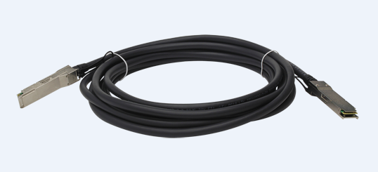

QSFP+ cables are hot swappable.
- Wear an ESD wrist strap or ESD gloves when installing PCIe cables.
- Prevent the cables from being twisted.
Installation Procedure
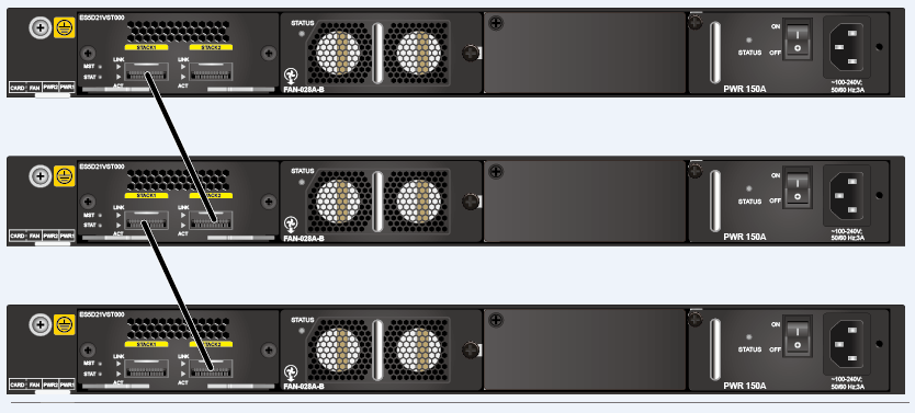
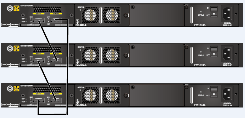
Two stack topologies are available: chain topology and ring topology, as shown in Figure 2 and Figure 3. For comparison of the two topologies, see Stack Setup.
Power off the switch before connecting PCIe stack cables.
When connecting stack cables, connect port STACK 1 of one switch to port STACK 2 of another switch.
- Wear an ESD wrist strap and connect the other end of the strap to the ESD jack on the cabinet.
- Use stack cables to connect SwitchA and SwitchB.
- Power on SwitchA and then SwitchB.
- Check whether SwitchA and SwitchB have set up a stack successfully. (See Checking Whether a Stack Has Been Established Through Stack Card Connections.)
- Use stack cables to connect SwitchC and SwitchB, and then power on SwitchC.
- Check whether SwitchA, SwitchB, and SwitchC have set up a stack successfully. (See Checking Whether a Stack Has Been Established Through Stack Card Connections.)
To specify a member switch as the master switch, power on that switch first. Power on the other member switches after that switch has started. In this example, SwitchA becomes the master switch after the stack is set up.