Stack Setup
Physical connection setup
Multiple switches are connected in a required topology using the appropriate connection mode to establish a stack network.
Master election
Member switches exchange stack competition packets and elect the master switch according to master election rules.
Stack ID assignment and standby switch election
The master switch collects topology information from other member switches and assigns them stack IDs; the standby switch is elected.
Software version and configuration file synchronization
The master switch synchronizes the topology of the stack to all member switches, and member switches synchronize their system software version and configuration files with the master switch. The stack is set up.
Physical Connection Setup
Topology |
Advantage |
Disadvantage |
Usage Scenario |
|---|---|---|---|
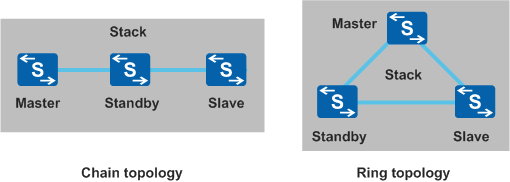
Chain topology |
Applicable for long-distance stacking because the first and last member switches do not need to be physically connected. |
|
Member switches are far from one another and a ring topology is difficult to deploy. |
Ring topology |
|
The first and last member switches need to be physically connected, which makes long-distance stacking difficult. |
Member switches are located near one another. |
Master Election
Determine the stack connection mode and topology, connect the member switches with physical links, and then power on all member switches. These member switches elect the master switch, which manages the stack. The master switch is elected based on the following rules (the election ends when a winning switch is found):
The switch that starts first becomes the master switch.
The master election timeout interval is 20 seconds. The startup process may take different lengths of time on different member switches. When stack member switches are powered on or restart, some member switches may not participate in the first master election. When a switch that starts 20s later joins the stack, the master switch is elected again. If the previous master switch fails the election, it restarts and then joins the stack as a non-master switch. If the switch that starts later fails the election, it can join the stack only as a non-master switch. For details, see Adding and Removing a Stack Member. If you want a specific switch to act as the master switch, power on that switch first, and power on the other switches after this switch starts.
To ensure that master election is completed at a time, you are advised to use switches of the same model to set up a stack. If you want to set up a stack of different switch models, you are advised to connect switches of the same model together.
For example, three switches A, B, and C set up a stack in a chain topology.- If A and B start first and C starts later, C joins the stack only as a non-master switch.
- If A and C start first and become the master switches, A and C compete to be the master switch based on their startup time when B starts and joins the stack. The switch that fails the election restarts and joins the stack as a non-master switch.
For example, four switches A, B, C, and D set up a stack in ring topology:- If A and B start first and C and D start later, C and D join the stack only as non-master switches.
- If A and C start first and become the master switches, A and C compete to be the master switch based on their startup time when B and D start and join the stack. The switch that fails the election restarts and joins the stack as a non-master switch.
If multiple switches complete startup at the same time, the switch with the highest stack priority becomes the master switch.
If multiple switches complete startup at the same time and have the same stack priority, the switch with the smallest MAC address becomes the master switch.
Stack ID Assign and Standby Switch Election
- The switch with the highest stack priority becomes the standby switch.
- If the switches have the same stack priority, the one with the smallest MAC address becomes the standby switch.
The election ends when a winning switch is found. After the standby switch is elected, all the other member switches join the stack as slave switches.
Software Version and Configuration File Synchronization
Automatic software loading: If the standby and slave switches are running a different software version than the master switch, the standby and slave switches download the master switch system software, restart with the new system software, and rejoin the stack. Member switches must have compatible software versions with one another to set up a stack.
Configuration file synchronization: The master switch has the startup and running configuration files for the stack, the standby and slave switches download the master switch configuration file and apply it. This mechanism enables member switches to work like a single switch and ensures that other switches continue working normally if the master switch fails. For details about the configuration file, see Configuration File.