Example for Establishing a Stack Using Stack Card Connections
Networking Requirements
An enterprise network needs to provide a sufficient number of ports to access devices, but a simple network structure is required to facilitate configuration and maintenance.
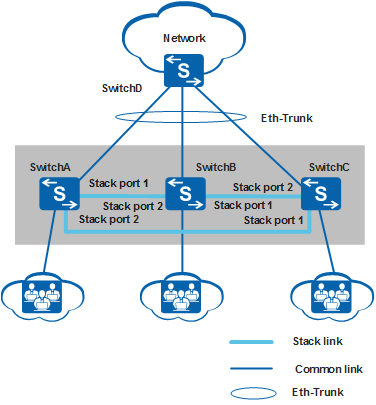
As shown in Figure 1, SwitchA, SwitchB, and SwitchC need to set up a stack with a ring topology and connect to SwitchD through inter-device Eth-Trunks. SwitchA, SwitchB, and SwitchC are the master, standby, and slave switches respectively, with stack IDs of 0, 1, and 2 and stack priorities of 200, 100, and 100. As they function as a single logical device on the network, the number of ports increases while keeping network management and maintenance relatively simple.
The S5720-C-EI series switches are used on the network.
Configuration Roadmap
Power off the switches, install one ES5D21VST000 stack card on each switch, and power on the switches.
Configure stack IDs and stack priorities for member switches to facilitate management.
Power off SwitchA, SwitchB, and SwitchC. Connect stack ports using QSFP+ cables according to Figure 1 and power on the switches.
Configure inter-device Eth-Trunks to increase reliability and uplink bandwidth.

When connecting stack cables, connect STACK1 port of one switch to STACK2 port of another switch.
If SwitchA, SwitchB, and SwitchC are different switch models, these models must be able to set up a stack together. For details, see Stack Support and Version Requirements.
During a stack setup, the software version used by the master switch takes effect, and the standby and slave switches synchronize their software versions with the software version of the master switch.
Procedure
- Install the ES5D21VST000 stack card.
Install the ES5D21VST000 stack card on SwitchA, SwitchB, and SwitchC. For details on how to install a stack card, see Installing a Stack Card.
- To help identify devices, set device
names as SwitchA, SwitchB, and SwitchC. The following uses SwitchA
as an example.
<HUAWEI> system-view
[HUAWEI] sysname SwitchA
- Configure stack IDs and stack priorities.
# Set the stack priority of SwitchA to 200.
[SwitchA] stack slot 0 priority 200
Warning:Please do not frequently modify Priority because it will make the stack split. Continue? [Y/N]:y
# Set the stack ID of SwitchB to 1.
[SwitchB] stack slot 0 renumber 1
Warning: All the configurations related to the slot ID will be lost after the slot ID is modified.
Please do not frequently modify slot ID because it will make the stack split. Continue? [Y/N]:y
Info: Stack configuration has been changed, and the device needs to restart to make the configuration effective.
# Set the stack ID of SwitchC to 2.
[SwitchC] stack slot 0 renumber 2
Warning: All the configurations related to the slot ID will be lost after the slot ID is modified.
Please do not frequently modify slot ID because it will make the stack split. Continue? [Y/N]:y
Info: Stack configuration has been changed, and the device needs to restart to make the configuration effective.
- Power off SwitchA, SwitchB, and SwitchC, connect stack
ports using QSFP+ cables, and power them
on.
- Run the save command to save the configurations before you power off the switches.
- The STACK1 port of one switch must be connected to the STACK2 port of another switch. Otherwise, the stack cannot be set up.
- To ensure that the stack has been successfully established,
connect and power on the switches in the following sequence. (To specify
a member switch as the master switch, power on that switch first.
In this example, SwitchA is the master switch.)
- Power off SwitchA, SwitchB, and SwitchC.
- Connect SwitchA and SwitchB with a stack cable.
- Power on and start SwitchA and then power on SwitchB.
- Check whether SwitchA and SwitchB have set up a stack successfully. For the verification method, see Checking Whether a Stack Has Been Established Through Stack Card Connections.
- Connect SwitchC to SwitchB and SwitchA using stack cables and then power on SwitchC.
- Check whether SwitchA, SwitchB, and SwitchC have set up a stack successfully. For the verification method, see Checking Whether a Stack Has Been Established Through Stack Card Connections.
- Configure inter-device Eth-Trunks.
Configure inter-device Eth-Trunk uplinks for the stack. For the detailed configuration process, see Example for Configuring Stack Eth-Trunks.
- Verify the configuration.
# Check basic stack information.
<SwitchA> display stack
Stack mode: Card
Stack topology type: Ring
Stack system MAC: 0200-0000-01ab
MAC switch delay time: 10 min
Stack reserved vlan: 4093
Slot of the active management port: 0
Slot      Role        Mac address      Priority   Device type
-------------------------------------------------------------
    0     Master      0200-0000-01ab   200        S5720-36C-EI-AC
    1     Standby     0200-0000-0000   100        S5720-36C-EI-AC
    2     Slave       0200-0000-02aa   100        S5720-36C-EI-AC