Example for Configuring HoVPN
Networking Requirements
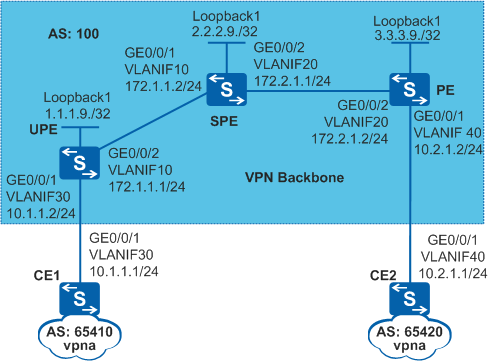
- The SPE is located on the provincial backbone network and connects to the city MPLS VPN network.
- The UPE is located on the city network and connects to VPN users.
The routing and forwarding capabilities of the UPE are lower than those of the SPE and PE. The HoVPN networking can enable users in vpna to communicate with each other while reducing the loads on the UPE.
Configuration Roadmap
The configuration roadmap is as follows:
- Configure an IGP on the backbone network to implement IP interworking.
- Configure basic MPLS capabilities and MPLS LDP on the backbone network to establish MPLS LSPs.
- Establish MP-IBGP peer relationships between the UPE and SPE and between the PE and SPE to exchange VPN routing information.
- On the UPE and PE, create VPN instances and establish EBGP peer relationships with CEs to exchange VPN routing information.
- On the SPE, create a VPN instance and specify the UPE as its underlayer PE (or user-end PE). Advertise the default route of the VPN instance to the UPE to reduce the loads on the UPE.
Procedure
- Configure VLANs on interfaces and assign IP addresses to the VLANIF interfaces and loopback interfaces according to Figure 1.
# Configure UPE.
<HUAWEI> system-view
[HUAWEI] sysname UPE
[UPE] interface loopback 1
[UPE-LoopBack1] ip address 1.1.1.9 32
[UPE-LoopBack1] quit
[UPE] vlan batch 10 30
[UPE] interface gigabitethernet 0/0/1
[UPE-GigabitEthernet0/0/1] port link-type trunk
[UPE-GigabitEthernet0/0/1] port trunk allow-pass vlan 30
[UPE-GigabitEthernet0/0/1] quit
[UPE] interface gigabitethernet 0/0/2
[UPE-GigabitEthernet0/0/2] port link-type trunk
[UPE-GigabitEthernet0/0/2] port trunk allow-pass vlan 10
[UPE-GigabitEthernet0/0/2] quit
[UPE] interface vlanif 10
[UPE-Vlanif10] ip address 172.1.1.1 255.255.255.0
[UPE-Vlanif10] quit
The configuration on SPE2, PE, CE1, and CE2 is similar to the configuration on PE1 and is not mentioned here.
- Configure OSPF on the backbone network to implement IP interworking.
# Configure the UPE.
[UPE] ospf 1
[UPE-ospf-1] area 0
[UPE-ospf-1-area-0.0.0.0] network 1.1.1.9 0.0.0.0
[UPE-ospf-1-area-0.0.0.0] network 172.1.1.0 0.0.0.255
[UPE-ospf-1-area-0.0.0.0] quit
[UPE-ospf-1] quit
The configuration on the SPE and PE is similar to the configuration on the UPE and is not mentioned here.
After the configuration is complete, OSPF neighbor relationships are established between the UPE and SPE, and between the SPE and PE. Run the display ospf peer command on these devices. The command output shows that the neighbor relationships are in Full state. Run the display ip routing-table command on these devices. The command output shows that they have learned the route to the loopback interface of each other.
- Configure basic MPLS capabilities and MPLS LDP on the backbone network to establish LDP LSPs.
# Configure the UPE.
[UPE] mpls lsr-id 1.1.1.9
[UPE] mpls
[UPE-mpls] quit
[UPE] mpls ldp
[UPE-mpls-ldp] quit
[UPE] interface vlanif 10
[UPE-Vlanif10] mpls
[UPE-Vlanif10] mpls ldp
[UPE-Vlanif10] quit
The configuration on the SPE and PE is similar to the configuration on the UPE and is not mentioned here.
After the configuration is complete, LDP sessions are established between the UPE and SPE, and between the SPE and PE. Run the display mpls ldp session command on these devices. The command output shows that the Status is Operational. Run the display mpls ldp lsp command. Information about the established LDP LSPs is displayed.
- Establish MP-IBGP peer relationships between the UPE and SPE and between the PE and SPE.
# Configure the UPE.
[UPE] bgp 100
[UPE-bgp] peer 2.2.2.9 as-number 100
[UPE-bgp] peer 2.2.2.9 connect-interface loopback 1
[UPE-bgp] ipv4-family vpnv4
[UPE-bgp-af-vpnv4] peer 2.2.2.9 enable
[UPE-bgp-af-vpnv4] quit
[UPE-bgp] quit
# Configure the SPE.
[SPE] bgp 100
[SPE-bgp] peer 1.1.1.9 as-number 100
[SPE-bgp] peer 1.1.1.9 connect-interface loopback 1
[SPE-bgp] peer 3.3.3.9 as-number 100
[SPE-bgp] peer 3.3.3.9 connect-interface loopback 1
[SPE-bgp] ipv4-family vpnv4
[SPE-bgp-af-vpnv4] peer 1.1.1.9 enable
[SPE-bgp-af-vpnv4] peer 3.3.3.9 enable
[SPE-bgp-af-vpnv4] quit
[SPE-bgp] quit
# Configure the PE.
[PE] bgp 100
[PE-bgp] peer 2.2.2.9 as-number 100
[PE-bgp] peer 2.2.2.9 connect-interface loopback 1
[PE-bgp] ipv4-family vpnv4
[PE-bgp-af-vpnv4] peer 2.2.2.9 enable
[PE-bgp-af-vpnv4] quit
[PE-bgp] quit
- On the UPE and PE, create VPN instances and establish EBGP peer relationships with the CEs.
# Configure the UPE.
[UPE] ip vpn-instance vpna
[UPE-vpn-instance-vpna] ipv4-family
[UPE-vpn-instance-vpna-af-ipv4] route-distinguisher 100:1
[UPE-vpn-instance-vpna-af-ipv4] vpn-target 1:1
[UPE-vpn-instance-vpna-af-ipv4] quit
[UPE-vpn-instance-vpna] quit
[UPE] interface vlanif 30
[UPE-Vlanif30] ip binding vpn-instance vpna
[UPE-Vlanif30] ip address 10.1.1.2 24
[UPE-Vlanif30] quit
[UPE] bgp 100
[UPE-bgp] ipv4-family vpn-instance vpna
[UPE-bgp-vpna] peer 10.1.1.1 as-number 65410
[UPE-bgp-vpna] import-route direct
[UPE-bgp-vpna] quit
[UPE-bgp] quit
# Configure CE1.
[CE1] interface vlanif 30
[CE1-Vlanif30] ip address 10.1.1.1 24
[CE1-Vlanif30] quit
[CE1] bgp 65410
[CE1-bgp] peer 10.1.1.2 as-number 100
[CE1-bgp] import-route direct
[CE1-bgp] quit
# Configure the PE.
[PE] ip vpn-instance vpna
[PE-vpn-instance-vpna] ipv4-family
[PE-vpn-instance-vpna-af-ipv4] route-distinguisher 100:2
[PE-vpn-instance-vpna-af-ipv4] vpn-target 1:1
[PE-vpn-instance-vpna-af-ipv4] quit
[PE-vpn-instance-vpna] quit
[PE] interface vlanif 40
[PE-Vlanif40] ip binding vpn-instance vpna
[PE-Vlanif40] ip address 10.2.1.2 24
[PE-Vlanif40] quit
[PE] bgp 100
[PE-bgp] ipv4-family vpn-instance vpna
[PE-bgp-vpna] peer 10.2.1.1 as-number 65420
[PE-bgp-vpna] import-route direct
[PE-bgp-vpna] quit
[PE-bgp] quit
# Configure CE2.
[CE2] interface vlanif 40
[CE2-Vlanif40] ip address 10.2.1.1 24
[CE2-Vlanif40] quit
[CE2] bgp 65420
[CE2-bgp] peer 10.2.1.2 as-number 100
[CE2-bgp] import-route direct
[CE2-bgp] quit
After the configuration is complete, run the display ip vpn-instance verbose command on the UPE and PE to check the configuration of VPN instances. Run the ping -vpn-instance command on the UPE and PE to ping the connected CEs. The ping operations succeed.

If a PE has multiple interfaces bound to the same VPN instance, specify a source IP addresses by setting -a source-ip-address in the ping -vpn-instance vpn-instance-name -a source-ip-address dest-ip-address command to ping a remote CE. If the source IP address is not specified, the ping operation fails.
- On the SPE, create a VPN instance, specify the UPE as its underlayer PE, and advertise the default route of the VPN instance to the UPE.
# Configure the VPN instance.
[SPE] ip vpn-instance vpna
[SPE-vpn-instance-vpna] route-distinguisher 200:1
[SPE-vpn-instance-vpna-af-ipv4] vpn-target 1:1
[SPE-vpn-instance-vpna-af-ipv4] quit
[SPE-vpn-instance-vpna] quit
# Specify the UPE for the SPE.
[SPE] bgp 100
[SPE-bgp] ipv4-family vpnv4
[SPE-bgp-af-vpnv4] peer 1.1.1.9 upe
# Advertise the default route of the VPN instance to the UPE.
[SPE-bgp-af-vpnv4] peer 1.1.1.9 default-originate vpn-instance vpna
[SPE-bgp-af-vpnv4] quit
[SPE-bgp] quit
- Verify the configurations.
After the configuration is complete, CE1 has no route to the network segment of the interface on CE2, but CE1 has a default route with the next hop as UPE. CE2 has a BGP route to the network segment of the interface on CE1. CE1 and CE2 can ping each other.
[CE1] display ip routing-table
Route Flags: R - relay, D - download to fib, T - to vpn-instance
------------------------------------------------------------------------------
Routing Tables: Public
         Destinations : 5        Routes : 5

  Destination/Mask  Proto  Pre  Cost      Flags  NextHop             Interface

        0.0.0.0/0   EBGP   255  0             D  10.1.1.2            Vlanif30
       10.1.1.0/24  Direct 0    0             D  10.1.1.1            Vlanif30
       10.1.1.1/32  Direct 0    0             D  127.0.0.1           Vlanif30
      127.0.0.0/8   Direct 0    0             D  127.0.0.1           InLoopBack0
      127.0.0.1/32  Direct 0    0             D  127.0.0.1           InLoopBack0
[CE1] ping 10.2.1.1 PING 10.2.1.1: 56 data bytes, press CTRL_C to break Reply from 10.2.1.1: bytes=56 Sequence=1 ttl=253 time=85 ms Reply from 10.2.1.1: bytes=56 Sequence=2 ttl=253 time=70 ms Reply from 10.2.1.1: bytes=56 Sequence=3 ttl=253 time=57 ms Reply from 10.2.1.1: bytes=56 Sequence=4 ttl=253 time=66 ms Reply from 10.2.1.1: bytes=56 Sequence=5 ttl=253 time=55 ms --- 10.2.1.1 ping statistics --- 5 packet(s) transmitted 5 packet(s) received 0.00% packet loss round-trip min/avg/max = 55/66/85 ms[CE2] display ip routing-table Route Flags: R - relay, D - download to fib, T - to vpn-instance ------------------------------------------------------------------------------ Routing Tables: Public Destinations : 5 Routes : 5 Destination/Mask Proto Pre Cost Flags NextHop Interface 10.1.1.0/24 EBGP 255 0 D 10.2.1.2 Vlanif40 10.2.1.0/24 Direct 0 0 D 10.2.1.1 Vlanif40 10.2.1.1/32 Direct 0 0 D 127.0.0.1 Vlanif40 127.0.0.0/8 Direct 0 0 D 127.0.0.1 InLoopBack0 127.0.0.1/32 Direct 0 0 D 127.0.0.1 InLoopBack0Run the display bgp vpnv4 all routing-table command on the UPE. The command output shows a default route of vpna with the next hop as SPE.
[UPE] display bgp vpnv4 all routing-table


 BGP Local router ID is 1.1.1.9
 Status codes: * - valid, > - best, d - damped,
               h - history,  i - internal, s - suppressed, S - Stale
               Origin : i - IGP, e - EGP, ? - incomplete


 Total number of routes from all PE: 4
 Route Distinguisher: 100:1


      Network            NextHop        MED        LocPrf    PrefVal Path/Ogn

 *>   10.1.1.0/24        0.0.0.0         0                     0      ?
 *                       10.1.1.1        0                     0      65410?
 *>   10.1.1.2/32        0.0.0.0         0                     0      ?

 Route Distinguisher: 200:1


      Network            NextHop        MED        LocPrf    PrefVal Path/Ogn

 *>i  0.0.0.0            2.2.2.9         0          100        0      i

 VPN-Instance vpna, Router ID 1.1.1.9:

 Total Number of Routes: 4
      Network            NextHop        MED        LocPrf    PrefVal Path/Ogn

 *>i  0.0.0.0            2.2.2.9         0          100        0      i
 *>   10.1.1.0/24        0.0.0.0         0                     0      ?
                         10.1.1.1        0                     0      65410?
 *>   10.1.1.2/32        0.0.0.0         0                     0      ?
Configuration Files
CE1 configuration file
#
sysname CE1
#
vlan batch 30
#
interface VLanif30
 ip address 10.1.1.1 255.255.255.0
#
interface GigabitEthernet0/0/1
 port link-type trunk
 port trunk allow-pass vlan 30
#
bgp 65410
 peer 10.1.1.2 as-number 100
 #
 ipv4-family unicast
  undo synchronization
  import-route direct
  peer 10.1.1.2 enable
#
return
UPE configuration file
#
sysname UPE
#
vlan batch 10 30
#
ip vpn-instance vpna
 ipv4-family
  route-distinguisher 100:1
  vpn-target 1:1 export-extcommunity
  vpn-target 1:1 import-extcommunity
#
mpls lsr-id 1.1.1.9
mpls
#
mpls ldp
#
interface Vlanif10
 ip address 172.1.1.1 255.255.255.0
 mpls
 mpls ldp
#
interface Vlanif30
 ip binding vpn-instance vpna
 ip address 10.1.1.2 255.255.255.0
#
interface GigabitEthernet0/0/1
 port link-type trunk
 port trunk allow-pass vlan 30
#
interface GigabitEthernet0/0/2
 port link-type trunk
 port trunk allow-pass vlan 10
#
interface LoopBack1
 ip address 1.1.1.9 255.255.255.255
#
bgp 100
 peer 2.2.2.9 as-number 100
 peer 2.2.2.9 connect-interface LoopBack1
 #
 ipv4-family unicast
  undo synchronization
  peer 2.2.2.9 enable
 #
 ipv4-family vpnv4
  policy vpn-target
  peer 2.2.2.9 enable
 #
 ipv4-family vpn-instance vpna
  peer 10.1.1.1 as-number 65410
  import-route direct
#
ospf 1
 area 0.0.0.0
  network 1.1.1.9 0.0.0.0
  network 172.1.1.0 0.0.0.255
#
return
SPE configuration file
#
sysname SPE
#
vlan batch 10 20
#
ip vpn-instance vpna
 ipv4-family
  route-distinguisher 200:1
  vpn-target 1:1 export-extcommunity
  vpn-target 1:1 import-extcommunity
#
mpls lsr-id 2.2.2.9
mpls
#
mpls ldp
#
interface Vlanif10
 ip address 172.1.1.2 255.255.255.0
 mpls
 mpls ldp
#
interface Vlanif20
 ip address 172.2.1.1 255.255.255.0
 mpls
 mpls ldp
#
interface GigabitEthernet0/0/1
 port link-type trunk
 port trunk allow-pass vlan 10
#
interface GigabitEthernet0/0/2
 port link-type trunk
 port trunk allow-pass vlan 20
#
interface LoopBack1
 ip address 2.2.2.9 255.255.255.255
#
bgp 100
 peer 1.1.1.9 as-number 100
 peer 3.3.3.9 as-number 100
 peer 1.1.1.9 connect-interface LoopBack1
 peer 3.3.3.9 connect-interface LoopBack1
 #
 ipv4-family unicast
  undo synchronization
  peer 1.1.1.9 enable
  peer 3.3.3.9 enable
 #
 ipv4-family vpnv4
  policy vpn-target
  peer 1.1.1.9 enable
  peer 1.1.1.9 upe
  peer 1.1.1.9 default-originate vpn-instance vpna
  peer 3.3.3.9 enable
#
ospf 1
 area 0.0.0.0
  network 2.2.2.9 0.0.0.0
  network 172.1.1.0 0.0.0.255
  network 172.2.1.0 0.0.0.255
#
return
PE configuration file
#
sysname PE
#
vlan batch 20 40
#
ip vpn-instance vpna
 ipv4-family
  route-distinguisher 100:2
  vpn-target 1:1 export-extcommunity
  vpn-target 1:1 import-extcommunity
#
mpls lsr-id 3.3.3.9
mpls
#
mpls ldp
#
interface Vlanif20
 ip address 172.2.1.2 255.255.255.0
 mpls
 mpls ldp
#
interface Vlanif40
 ip binding vpn-instance vpna
 ip address 10.2.1.2 255.255.255.0
#
interface GigabitEthernet0/0/1
 port link-type trunk
 port trunk allow-pass vlan 40
#
interface GigabitEthernet0/0/2
 port link-type trunk
 port trunk allow-pass vlan 20
#
interface LoopBack1
 ip address 3.3.3.9 255.255.255.255
#
bgp 100
 peer 2.2.2.9 as-number 100
 peer 2.2.2.9 connect-interface LoopBack1
 #
 ipv4-family unicast
  undo synchronization
  peer 2.2.2.9 enable
 #
 ipv4-family vpnv4
  policy vpn-target
  peer 2.2.2.9 enable
 #
 ipv4-family vpn-instance vpna
  peer 10.2.1.1 as-number 65420
  import-route direct
#
ospf 1
 area 0.0.0.0
  network 3.3.3.9 0.0.0.0
  network 172.2.1.0 0.0.0.255
#
return
CE2 configuration file
#
sysname CE2
#
vlan batch 40
#
interface Vlanif40
 ip address 10.2.1.1 255.255.255.0
#
interface GigabitEthernet0/0/1
 port link-type trunk
 port trunk allow-pass vlan 40
#
bgp 65420
 peer 10.2.1.2 as-number 100
 #
 ipv4-family unicast
  undo synchronization
  import-route direct
  peer 10.2.1.2 enable
#
return