Example for Configuring BGP AS Number Substitution
Networking Requirements
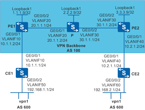
As shown in Figure 1, CE1 and CE2 belong to the same VPN. CE1 connects to PE1, and CE2 connects to PE2. Both CE1 and CE2 use AS number 600.
The PEs and CEs need to establish EBGP peer relationships to allow communication between VPN users.
Configuration Roadmap
The configuration roadmap is as follows:
Configure OSPF between the P and PEs to ensure IP connectivity on the backbone network.
Configure basic MPLS capabilities and MPLS LDP on the P and PEs to establish MPLS LSP tunnels for VPN data transmission on the backbone network.
Establish MP-IBGP peer relationships between PEs to exchange VPNv4 routes.
Configure a VPN instance and set the VPN target to 1:1 on PE1 and PE2 so that users in the VPN can communicate with each other. Bind the PE interfaces connected to CEs to the corresponding VPN instances to provide access for VPN users.
Establish EBGP peer relationships between PEs and CEs and import routes of the CEs into routing tables of the PEs.
Configure BGP AS number substitution on the PEs to enable them to accept routes with the local AS number.
Procedure
- Configure basic BGP/MPLS IP VPN functions.
The configurations include the following:
Configure OSPF on the MPLS backbone network so that the PEs and P can learn the routes to the loopback interface of each other.
Configure basic MPLS capabilities and MPLS LDP on the backbone network to establish LDP LSPs on the MPLS backbone network.
Establish MP-IBGP peer relationships between PEs to exchange VPNv4 routes.
Configure a VPN instance of vpn1 on PE2 and bind the interface connected to CE2 to the VPN instance.
Configure a VPN instance of vpn1 on PE1 and bind the interface connected to CE1 to the VPN instance.
Establish BGP peer relationships between PE1 and CE1 and between PE2 and CE2 to import routes of the CEs to the PEs.
For detailed configuration, refer to Example for Configuring BGP/MPLS IP VPN.
After the configuration is complete, run the display ip routing-table command on CE2 to check the routing table. The routing table on CE2 contains the route to the network segment (10.1.1.0/24) of interface that connects CE1 to PE1 but contains no route to the VPN (192.168.1.0/24) of CE1. This is the same on CE1.
[CE2] display ip routing-table
Route Flags: R - relay, D - download to fib, T - to vpn-instance
------------------------------------------------------------------------------
Routing Tables: Public
         Destinations : 7        Routes : 7
  Destination/Mask  Proto  Pre  Cost     Flags  NextHop         Interface
       10.1.1.0/24  EBGP   255  0        D      10.2.1.2        Vlanif40
       10.2.1.0/24  Direct 0    0        D      10.2.1.1        Vlanif40
       10.2.1.1/32  Direct 0    0        D      127.0.0.1       Vlanif40
       127.0.0.0/8  Direct 0    0        D      127.0.0.1       InLoopBack0
      127.0.0.1/32  Direct 0    0        D      127.0.0.1       InLoopBack0
    192.168.2.0/24  Direct 0    0        D      192.168.2.1     Vlanif60
    192.168.2.1/32  Direct 0    0        D      127.0.0.1       Vlanif60
Run the display ip routing-table vpn-instance command on the PEs to check the routing table of the VPN instance. The VPN routing table has routes to the VPN of the CEs.
The information displayed on PE2 is used as an example.
[PE2] display ip routing-table vpn-instance vpn1
Route Flags: R - relay, D - download to fib, T - to vpn-instance
------------------------------------------------------------------------------
Routing Tables: vpn1
          Destinations : 5        Routes : 5
  Destination/Mask  Proto  Pre  Cost     Flags  NextHop         Interface
       10.1.1.0/24  IBGP   255  0        RD     1.1.1.9         Vlanif30
       10.2.1.0/24  Direct 0    0        D      10.2.1.2        Vlanif40
       10.2.1.2/32  Direct 0    0        D      127.0.0.1       Vlanif40
    192.168.1.0/24  IBGP   255  0        RD     1.1.1.9         Vlanif30
    192.168.2.0/24  EBGP   255  0        D      10.2.1.1        Vlanif40
Run the display bgp routing-table peer received-routes command on CE2. The command output shows that CE2 did not accept the route to 192.168.1.0/24.
[CE2] display bgp routing-table peer 10.2.1.2 received-routes BGP Local router ID is 10.2.1.1 Status codes: * - valid, > - best, d - damped, h - history, i - internal, s - suppressed, S - Stale Origin : i - IGP, e - EGP, ? - incomplete Total Number of Routes: 2 Network NextHop MED LocPrf PrefVal Path/Ogn *> 10.1.1.0/24 10.2.1.2 0 100? 10.2.1.0/24 10.2.1.2 0 0 100? - Configure BGP AS number substitution.
Configure BGP AS number substitution on PEs.
# Configure PE2. PE2 is used as an example.
[PE2] bgp 100
[PE2-bgp] ipv4-family vpn-instance vpn1
[PE2-bgp-vpn1] peer 10.2.1.1 substitute-as
[PE2-bgp-vpn1] quit
[PE2-bgp] quit
In the route advertised to CE2 by PE2, the AS path attribute of 192.168.1.0/24 changes from "100 600" to "100 100".
Feb 22 2013 16:35:18.670.4-08:00 PE2 RM/6/RMDEBUG:
BGP.vpn1: Send UPDATE to 10.2.1.1 for following destinations :

MP_reach  : AFI/SAFI  1/1
Origin    : Incomplete
AS Path   : 100 100
Next Hop  : 10.2.1.2
192.168.1.0/24,
Check the routing information accepted by CE2 and routing table of CE2.
[CE2] display bgp routing-table peer 10.2.1.2 received-routes

 BGP Local router ID is 10.2.1.1
 Status codes: * - valid, > - best, d - damped,
               h - history,  i - internal, s - suppressed, S - Stale
               Origin : i - IGP, e - EGP, ? - incomplete


 Total Number of Routes: 3
      Network            NextHop        MED        LocPrf    PrefVal Path/Ogn

 *>   10.1.1.0/24        10.2.1.2                              0      100?
      10.2.1.0/24        10.2.1.2        0                     0      100?
 *> 192.168.1.0/24       10.2.1.2                              0      100 100?

[CE2] display ip routing-table
Route Flags: R - relay, D - download to fib, T - to vpn-instance
------------------------------------------------------------------------------
Routing Tables: Public
         Destinations : 8        Routes : 8
  Destination/Mask  Proto  Pre  Cost       Flags  NextHop         Interface
       10.1.1.0/24  EBGP   255  0          D      10.2.1.2        Vlanif40
       10.2.1.0/24  Direct 0    0          D      10.2.1.1        Vlanif40
       10.2.1.1/32  Direct 0    0          D      127.0.0.1       Vlanif40
       127.0.0.0/8  Direct 0    0          D      127.0.0.1       InLoopBack0
      127.0.0.1/32  Direct 0    0          D      127.0.0.1       InLoopBack0
    192.168.1.1/24  EBGP   255  0          D      10.2.1.2        Vlanif40
    192.168.2.0/24  Direct 0    0          D      127.0.0.1       Vlanif60
    192.168.2.1/32  Direct 0    0          D      127.0.0.1       Vlanif60
After configuring BGP AS number substitution on PE1, you can see that CE1 and CE2 can successfully ping each other.
[CE1] ping -a 192.168.1.1 192.168.2.1
  PING 192.168.2.1: 56  data bytes, press CTRL_C to break
    Reply from 192.168.2.1: bytes=56 Sequence=1 ttl=253 time=109 ms
    Reply from 192.168.2.1: bytes=56 Sequence=2 ttl=253 time=67 ms
    Reply from 192.168.2.1: bytes=56 Sequence=3 ttl=253 time=66 ms
    Reply from 192.168.2.1: bytes=56 Sequence=4 ttl=253 time=85 ms
    Reply from 192.168.2.1: bytes=56 Sequence=5 ttl=253 time=70 ms
  --- 192.168.2.1 ping statistics ---
    5 packet(s) transmitted
    5 packet(s) received
    0.00% packet loss
    round-trip min/avg/max = 66/79/109 ms
Configuration Files
CE1 configuration file
#
sysname CE1
#
vlan batch 10 50
#
interface Vlanif10
 ip address 10.1.1.1 255.255.255.0
#
interface Vlanif50
 ip address 192.168.1.1 255.255.255.0
#
interface GigabitEthernet0/0/1
 port link-type trunk
 port trunk allow-pass vlan 10
#
interface GigabitEthernet0/0/2
 port link-type trunk
 port trunk allow-pass vlan 50
#
bgp 600
 peer 10.1.1.2 as-number 100
 #
 ipv4-family unicast
  undo synchronization
  import-route direct
  peer 10.1.1.2 enable
#
return
PE1 configuration file
#
sysname PE1
#
vlan batch 10 20
#
ip vpn-instance vpn1
 ipv4-family
  route-distinguisher 100:1
  vpn-target 1:1 export-extcommunity
  vpn-target 1:1 import-extcommunity
#
mpls lsr-id 1.1.1.9
mpls
#
mpls ldp
#
interface Vlanif10
 ip binding vpn-instance vpn1
 ip address 10.1.1.2 255.255.255.0
#
interface Vlanif20
 ip address 20.1.1.1 255.255.255.0
 mpls
 mpls ldp
#
interface GigabitEthernet0/0/1
 port link-type trunk
 port trunk allow-pass vlan 10
#
interface GigabitEthernet0/0/2
 port link-type trunk
 port trunk allow-pass vlan 20
#
interface LoopBack1
 ip address 1.1.1.9 255.255.255.255
#
bgp 100
 peer 3.3.3.9 as-number 100
 peer 3.3.3.9 connect-interface LoopBack1
 #
 ipv4-family unicast
  undo synchronization
  peer 3.3.3.9 enable
 #
 ipv4-family vpnv4
  policy vpn-target
  peer 3.3.3.9 enable
 #
 ipv4-family vpn-instance vpn1
  peer 10.1.1.1 as-number 600
  peer 10.1.1.1 substitute-as
  import-route direct
#
ospf 1
 area 0.0.0.0
  network 1.1.1.9 0.0.0.0
  network 20.1.1.0 0.0.0.255
#
return
P configuration file
#
sysname P
#
vlan batch 20 30
#
mpls lsr-id 2.2.2.9
mpls
#
mpls ldp
#
interface Vlanif20
 ip address 20.1.1.2 255.255.255.0
 mpls
 mpls ldp
#
interface Vlanif30
 ip address 30.1.1.1 255.255.255.0
 mpls
 mpls ldp
#
interface GigabitEthernet0/0/1
 port link-type trunk
 port trunk allow-pass vlan 20
#
interface GigabitEthernet0/0/2
 port link-type trunk
 port trunk allow-pass vlan 30
#
interface LoopBack1
 ip address 2.2.2.9 255.255.255.255
#
ospf 1
 area 0.0.0.0
  network 2.2.2.9 0.0.0.0
  network 20.1.1.0 0.0.0.255
  network 30.1.1.0 0.0.0.255
#
return
PE2 configuration file
#
sysname PE2
#
vlan batch 30 40
#
ip vpn-instance vpn1
 ipv4-family
  route-distinguisher 100:1
  vpn-target 1:1 export-extcommunity
  vpn-target 1:1 import-extcommunity
#
mpls lsr-id 3.3.3.9
mpls
#
mpls ldp
#
interface Vlanif30
 ip address 30.1.1.2 255.255.255.0
 mpls
 mpls ldp
#
interface Vlanif40
 ip binding vpn-instance vpn1
 ip address 10.2.1.2 255.255.255.0
#
interface GigabitEthernet0/0/1
 port link-type trunk
 port trunk allow-pass vlan 40
#
interface GigabitEthernet0/0/2
 port link-type trunk
 port trunk allow-pass vlan 30
#
interface LoopBack1
 ip address 3.3.3.9 255.255.255.255
#
bgp 100
 peer 1.1.1.9 as-number 100
 peer 1.1.1.9 connect-interface LoopBack1
 #
 ipv4-family unicast
  undo synchronization
  peer 1.1.1.9 enable
 #
 ipv4-family vpnv4
  policy vpn-target
  peer 1.1.1.9 enable
 #
 ipv4-family vpn-instance vpn1
  peer 10.2.1.1 as-number 600
  peer 10.2.1.1 substitute-as
  import-route direct
#
ospf 1
 area 0.0.0.0
  network 3.3.3.9 0.0.0.0
  network 30.1.1.0 0.0.0.255
#
return
CE2 configuration file
#
sysname CE2
#
vlan batch 40 60
#
interface Vlanif40
 ip address 10.2.1.1 255.255.255.0
#
interface Vlanif60
 ip address 192.168.2.1 255.255.255.0
#
interface GigabitEthernet0/0/1
 port link-type trunk
 port trunk allow-pass vlan 40
#
interface GigabitEthernet0/0/2
 port link-type trunk
 port trunk allow-pass vlan 60
#
bgp 600
 peer 10.2.1.2 as-number 100
 #
 ipv4-family unicast
  undo synchronization
  import-route direct
  peer 10.2.1.2 enable
#
return