Example for Configuring an OSPF Sham Link
Networking Requirements
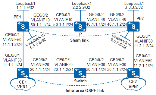
As shown in Figure 1, CE1 and CE2 belong to the same OSPF area of VPN1 and they connect to PE1 and PE2 respectively. The OSPF costs of all interfaces are 1.
The CEs and PEs need to run OSPF. When the backbone network is running properly, VPN traffic of CE1 and CE2 should be forwarded over the MPLS backbone network without passing through the OSPF intra-area routes.

In this scenario, to avoid loops, ensure that all connected interfaces have STP disabled and connected interfaces are removed from VLAN 1. If STP is enabled and VLANIF interfaces of switches are used to construct a Layer 3 ring network, an interface on the network will be blocked. As a result, Layer 3 services on the network cannot run normally.
Configuration Roadmap
The configuration roadmap is as follows:
Establish an ME-IBGP peer relationship between the PEs and configure OSPF between the PEs and CEs.
Configure VPN instances on PEs and bind the interfaces connected to CEs to the VPN instances.
Create an OSPF sham link on the PEs.
Set the cost value of the forwarding interface of the private network to be larger than the cost of the sham link so that VPN traffic is transmitted over the MPLS backbone network.
Procedure
- Configure OSPF on the customer network.
Configure OSPF on CE1, Switch, and CE2 and advertise the network segment of each interface.
# Configure CE1.
<HUAWEI> system-view
[HUAWEI] sysname CE1
[CE1] vlan batch 20 50
[CE1] interface gigabitethernet 0/0/2
[CE1-GigabitEthernet0/0/2] port link-type trunk
[CE1-GigabitEthernet0/0/2] port trunk allow-pass vlan 20
[CE1-GigabitEthernet0/0/2] quit
[CE1] interface gigabitethernet 0/0/1
[CE1-GigabitEthernet0/0/1] port link-type trunk
[CE1-GigabitEthernet0/0/1] port trunk allow-pass vlan 50
[CE1-GigabitEthernet0/0/1] quit
[CE1] interface vlanif 20
[CE1-Vlanif20] ip address 20.1.1.1 24
[CE1-Vlanif20] quit
[CE1] interface vlanif 50
[CE1-Vlanif50] ip address 11.1.1.1 24
[CE1-Vlanif50] quit
[CE1] ospf
[CE1-ospf-1] area 0
[CE1-ospf-1-area-0.0.0.0] network 20.1.1.0 0.0.0.255
[CE1-ospf-1-area-0.0.0.0] network 11.1.1.0 0.0.0.255
[CE1-ospf-1-area-0.0.0.0] quit
[CE1-ospf-1] quit
# Configure Switch.
<HUAWEI> system-view
[HUAWEI] sysname Switch
[Switch] vlan batch 20 30
[Switch] interface gigabitethernet 0/0/1
[Switch-GigabitEthernet0/0/1] port link-type trunk
[Switch-GigabitEthernet0/0/1] port trunk allow-pass vlan 20
[Switch-GigabitEthernet0/0/1] quit
[Switch] interface gigabitethernet 0/0/2
[Switch-GigabitEthernet0/0/2] port link-type trunk
[Switch-GigabitEthernet0/0/2] port trunk allow-pass vlan 30
[Switch-GigabitEthernet0/0/2] quit
[Switch] interface vlanif 20
[Switch-Vlanif20] ip address 20.1.1.2 24
[Switch-Vlanif20] quit
[Switch] interface vlanif 30
[Switch-Vlanif30] ip address 30.1.1.1 24
[Switch-Vlanif30] quit
[Switch] ospf
[Switch-ospf-1] area 0
[Switch-ospf-1-area-0.0.0.0] network 20.1.1.0 0.0.0.255
[Switch-ospf-1-area-0.0.0.0] network 30.1.1.0 0.0.0.255
[Switch-ospf-1-area-0.0.0.0] quit
[Switch-ospf-1] quit
# Configure CE2.
<HUAWEI> system-view
[HUAWEI] sysname CE2
[CE2] vlan batch 30 60
[CE2] interface gigabitethernet 0/0/2
[CE2-GigabitEthernet0/0/2] port link-type trunk
[CE2-GigabitEthernet0/0/2] port trunk allow-pass vlan 30
[CE2-GigabitEthernet0/0/2] quit
[CE2] interface gigabitethernet 0/0/1
[CE2-GigabitEthernet0/0/1] port link-type trunk
[CE2-GigabitEthernet0/0/1] port trunk allow-pass vlan 60
[CE2-GigabitEthernet0/0/1] quit
[CE2] interface vlanif 30
[CE2-Vlanif30] ip address 30.1.1.2 24
[CE2-Vlanif30] quit
[CE2] interface vlanif 60
[CE2-Vlanif60] ip address 11.2.1.1 24
[CE2-Vlanif60] quit
[CE2] ospf
[CE2-ospf-1] area 0
[CE2-ospf-1-area-0.0.0.0] network 30.1.1.0 0.0.0.255
[CE2-ospf-1-area-0.0.0.0] network 11.2.1.0 0.0.0.255
[CE2-ospf-1-area-0.0.0.0] quit
[CE2-ospf-1] quit
- Complete basic BGP/MPLS IP VPN configuration on the backbone
network: configure an IGP, enable MPLS and LDP, and establish an MP-IBGP
peer relationship between the PEs.
# Configure PE1.
<HUAWEI> system-view
[HUAWEI] sysname PE1
[PE1] vlan batch 10 50
[PE1] interface gigabitethernet 0/0/2
[PE1-GigabitEthernet0/0/2] port link-type trunk
[PE1-GigabitEthernet0/0/2] port trunk allow-pass vlan 10
[PE1-GigabitEthernet0/0/2] quit
[PE1] interface gigabitethernet 0/0/1
[PE1-GigabitEthernet0/0/1] port link-type trunk
[PE1-GigabitEthernet0/0/1] port trunk allow-pass vlan 50
[PE1-GigabitEthernet0/0/1] quit
[PE1] interface loopback 1
[PE1-LoopBack1] ip address 1.1.1.9 32
[PE1-LoopBack1] quit
[PE1] mpls lsr-id 1.1.1.9
[PE1] mpls
[PE1-mpls] quit
[PE1] mpls ldp
[PE1-mpls-ldp] quit
[PE1] interface vlanif 10
[PE1-Vlanif10] ip address 50.1.1.1 24
[PE1-Vlanif10] mpls
[PE1-Vlanif10] mpls ldp
[PE1-Vlanif10] quit
[PE1] ospf 1 router-id 1.1.1.9
[PE1-ospf-1] area 0
[PE1-ospf-1-area-0.0.0.0] network 1.1.1.9 0.0.0.0
[PE1-ospf-1-area-0.0.0.0] network 50.1.1.0 0.0.0.255
[PE1-ospf-1-area-0.0.0.0] quit
[PE1-ospf-1] quit
[PE1] bgp 100
[PE1-bgp] peer 3.3.3.9 as-number 100
[PE1-bgp] peer 3.3.3.9 connect-interface loopback 1
[PE1-bgp] ipv4-family vpnv4
[PE1-bgp-af-vpnv4] peer 3.3.3.9 enable
[PE1-bgp-af-vpnv4] quit
[PE1-bgp] quit
# Configure P.
<HUAWEI> system-view
[HUAWEI] sysname P
[P] vlan batch 10 40
[P] interface gigabitethernet 0/0/1
[P-GigabitEthernet0/0/1] port link-type trunk
[P-GigabitEthernet0/0/1] port trunk allow-pass vlan 10
[P-GigabitEthernet0/0/1] quit
[P] interface gigabitethernet 0/0/2
[P-GigabitEthernet0/0/2] port link-type trunk
[P-GigabitEthernet0/0/2] port trunk allow-pass vlan 40
[P-GigabitEthernet0/0/2] quit
[P] interface loopback 1
[P-LoopBack1] ip address 2.2.2.9 32
[P-LoopBack1] quit
[P] mpls lsr-id 2.2.2.9
[P] mpls
[P-mpls] quit
[P] mpls ldp
[P-mpls-ldp] quit
[P] interface vlanif 10
[P-Vlanif10] ip address 50.1.1.2 24
[P-Vlanif10] mpls
[P-Vlanif10] mpls ldp
[P-Vlanif10] quit
[P] interface vlanif 40
[P-Vlanif40] ip address 40.1.1.1 24
[P-Vlanif40] mpls
[P-Vlanif40] mpls ldp
[P-Vlanif40] quit
[P] ospf 1 router-id 2.2.2.9
[P-ospf-1] area 0
[P-ospf-1-area-0.0.0.0] network 2.2.2.9 0.0.0.0
[P-ospf-1-area-0.0.0.0] network 50.1.1.0 0.0.0.255
[P-ospf-1-area-0.0.0.0] network 40.1.1.0 0.0.0.255
[P-ospf-1-area-0.0.0.0] quit
[P-ospf-1] quit
# Configure PE2.
<HUAWEI> system-view
[HUAWEI] sysname PE2
[PE2] vlan batch 40 60
[PE2] interface gigabitethernet 0/0/1
[PE2-GigabitEthernet0/0/1] port link-type trunk
[PE2-GigabitEthernet0/0/1] port trunk allow-pass vlan 60
[PE2-GigabitEthernet0/0/1] quit
[PE2] interface gigabitethernet 0/0/2
[PE2-GigabitEthernet0/0/2] port link-type trunk
[PE2-GigabitEthernet0/0/2] port trunk allow-pass vlan 40
[PE2-GigabitEthernet0/0/2] quit
[PE2] interface loopback 1
[PE2-LoopBack1] ip address 3.3.3.9 32
[PE2-LoopBack1] quit
[PE2] mpls lsr-id 3.3.3.9
[PE2] mpls
[PE2-mpls] quit
[PE2] mpls ldp
[PE2-mpls-ldp] quit
[PE2] interface vlanif 40
[PE2-Vlanif40] ip address 40.1.1.2 24
[PE2-Vlanif40] mpls
[PE2-Vlanif40] mpls ldp
[PE2-Vlanif40] quit
[PE2] ospf 1 router-id 3.3.3.9
[PE2-ospf-1] area 0
[PE2-ospf-1-area-0.0.0.0] network 3.3.3.9 0.0.0.0
[PE2-ospf-1-area-0.0.0.0] network 40.1.1.0 0.0.0.255
[PE2-ospf-1-area-0.0.0.0] quit
[PE2-ospf-1] quit
[PE2] bgp 100
[PE2-bgp] peer 1.1.1.9 as-number 100
[PE2-bgp] peer 1.1.1.9 connect-interface loopback 1
[PE2-bgp] ipv4-family vpnv4
[PE2-bgp-af-vpnv4] peer 1.1.1.9 enable
[PE2-bgp-af-vpnv4] quit
[PE2-bgp] quit
After the configuration is complete, PE1 and PE2 can learn the route to the loopback interface of each other and establish an MP-IBGP peer relationship.
- Configure OSPF between the PEs and CEs.
# Configure PE1.
[PE1] ip vpn-instance vpn1
[PE1-vpn-instance-vpn1] ipv4-family
[PE1-vpn-instance-vpn1-af-ipv4] route-distinguisher 100:1
[PE1-vpn-instance-vpn1-af-ipv4] vpn-target 1:1
[PE1-vpn-instance-vpn1-af-ipv4] quit
[PE1-vpn-instance-vpn1] quit
[PE1] interface vlanif 50
[PE1-Vlanif50] ip binding vpn-instance vpn1
[PE1-Vlanif50] ip address 11.1.1.2 24
[PE1-Vlanif50] quit
[PE1] ospf 100 router-id 5.5.5.5 vpn-instance vpn1
[PE1-ospf-100] domain-id 10
[PE1-ospf-100] import-route bgp
[PE1-ospf-100] area 0
[PE1-ospf-100-area-0.0.0.0] network 11.1.1.0 0.0.0.255
[PE1-ospf-100-area-0.0.0.0] quit
[PE1-ospf-100] quit
[PE1] bgp 100
[PE1-bgp] ipv4-family vpn-instance vpn1
[PE1-bgp-vpn1] import-route direct
[PE1-bgp-vpn1] import-route ospf 100
[PE1-bgp-vpn1] quit
[PE1-bgp] quit
# Configure PE2.
[PE2] ip vpn-instance vpn1
[PE2-vpn-instance-vpn1] ipv4-family
[PE2-vpn-instance-vpn1-af-ipv4] route-distinguisher 100:2
[PE2-vpn-instance-vpn1-af-ipv4] vpn-target 1:1
[PE2-vpn-instance-vpn1-af-ipv4] quit
[PE2-vpn-instance-vpn1] quit
[PE2] interface vlanif 60
[PE2-Vlanif60] ip binding vpn-instance vpn1
[PE2-Vlanif60] ip address 11.2.1.2 24
[PE2-Vlanif60] quit
[PE2] ospf 100 router-id 6.6.6.6 vpn-instance vpn1
[PE2-ospf-100] import-route bgp
[PE2-   ospf-100] domain-id 10
[PE2-ospf-100] area 0
[PE2-ospf-100-area-0.0.0.0] network 11.2.1.0 0.0.0.255
[PE2-ospf-100-area-0.0.0.0] quit
[PE2-ospf-100] quit
[PE2] bgp 100
[PE2-bgp] ipv4-family vpn-instance vpn1
[PE2-bgp-vpn1] import-route direct
[PE2-bgp-vpn1] import-route ospf 100
[PE2-bgp-vpn1] quit
[PE2-bgp] quit
After the configuration is complete, run the display ip routing-table vpn-instance command on the PEs. The command output shows that the routes to the remote CEs are OSPF routes through the customer network, not the BGP routes through the backbone network.
The information displayed on PE1 is used as an example.
[PE1] display ip routing-table vpn-instance vpn1 Route Flags: R - relay, D - download to fib, T - to vpn-instance ------------------------------------------------------------------------------ Routing Tables: vpn1 Destinations : 5 Routes : 5 Destination/Mask Proto Pre Cost Flags NextHop Interface 11.1.1.0/24 Direct 0 0 D 11.1.1.2 Vlanif50 11.1.1.2/32 Direct 0 0 D 127.0.0.1 Vlanif50 11.2.1.0/24 OSPF 10 4 D 11.1.1.1 Vlanif50 20.1.1.0/24 OSPF 10 2 D 11.1.1.1 Vlanif50 30.1.1.0/24 OSPF 10 3 D 11.1.1.1 Vlanif50 - Configure an OSPF sham link.
To forward VPN traffic through the MPLS backbone network, ensure that the cost of the sham link is smaller than the cost of the OSPF route used for forwarding VPN traffic over the customer network. A commonly used method is to set the cost of the forwarding interface on the customer network to be larger than the cost of the sham link.
# Configure CE1.
[CE1] interface vlanif 20
[CE1-Vlanif20] ospf cost 10
[CE1-Vlanif20] quit
# Configure CE2.
[CE2] interface vlanif 30
[CE2-Vlanif30] ospf cost 10
[CE2-Vlanif30] quit
# Configure PE1.
[PE1] interface loopback 10
[PE1-LoopBack10] ip binding vpn-instance vpn1
[PE1-LoopBack10] ip address 5.5.5.5 32
[PE1-LoopBack10] quit
[PE1] ospf 100
[PE1-ospf-100] area 0
[PE1-ospf-100-area-0.0.0.0] sham-link 5.5.5.5 6.6.6.6 cost 1
[PE1-ospf-100-area-0.0.0.0] quit
[PE1-ospf-100] quit
# Configure PE2.
[PE2] interface loopback 10
[PE2-LoopBack10] ip binding vpn-instance vpn1
[PE2-LoopBack10] ip address 6.6.6.6 32
[PE2-LoopBack10] quit
[PE2] ospf 100
[PE2-ospf-100] area 0
[PE2-ospf-100-area-0.0.0.0] sham-link 6.6.6.6 5.5.5.5 cost 1
[PE2-ospf-100-area-0.0.0.0] quit
[PE2-ospf-100] quit
- Verify the configurations.
After the configuration is complete, run the display ip routing-table vpn-instance command on the PEs. The command output shows that the routes to the remote CEs are BGP routes through the backbone network, and there are routes to the destination of the sham link.
The information displayed on PE1 is used as an example.
[PE1] display ip routing-table vpn-instance vpn1
Route Flags: R - relay, D - download to fib, T - to vpn-instance
------------------------------------------------------------------------------
Routing Tables: vpn1
         Destinations : 7        Routes : 7
  Destination/Mask  Proto  Pre  Cost      Flags  NextHop           Interface
        5.5.5.5/32  Direct 0    0             D  127.0.0.1         LoopBack1
        6.6.6.6/32  IBGP   255  0            RD  3.3.3.9           Vlanif10
       11.1.1.0/24  Direct 0    0             D  11.1.1.2          Vlanif50
       11.1.1.2/32  Direct 0    0             D  127.0.0.1         Vlanif50
       11.2.1.0/24  IBGP   255  0            RD  3.3.3.9           Vlanif10
       20.1.1.0/24  OSPF   10   11            D  11.1.1.1          Vlanif50
       30.1.1.0/24  OSPF   10   12           RD  3.3.3.9           Vlanif50
Run the display ip routing-table command on a CE, and you can see that the cost of the OSPF route to the remote CE has changed to 3, and the next hop has changed to the VLANIF interface connected to the PE. That is, the VPN traffic to the remote CE is forwarded through the backbone network.
The information displayed on CE1 is used as an example.
[CE1] display ip routing-table
Route Flags: R - relay, D - download to fib, T - to vpn-instance
------------------------------------------------------------------------------
Routing Tables: Public
         Destinations : 10       Routes : 10
  Destination/Mask  Proto  Pre   Cost        Flags NextHop         Interface
        5.5.5.5/32  O_ASE  150   1              D  11.1.1.2        Vlanif50
        6.6.6.6/32  O_ASE  150   1              D  11.1.1.2        Vlanif50
       11.1.1.0/24  Direct 0     0              D  11.1.1.1        Vlanif50
       11.1.1.1/32  Direct 0     0              D  127.0.0.1       Vlanif50
       11.2.1.0/24  OSPF   10    3              D  11.1.1.2        Vlanif50
       20.1.1.0/24  Direct 0     0              D  20.1.1.1        Vlanif20
       20.1.1.1/32  Direct 0     0              D  127.0.0.1       Vlanif20
       30.1.1.0/24  OSPF   10    11             D  11.1.1.2        Vlanif20
      127.0.0.0/8   Direct 0     0              D  127.0.0.1       InLoopBack0
      127.0.0.1/32  Direct 0     0              D  127.0.0.1       InLoopBack0
Cost of the OSPF route from CE1 to CE2 = Cost of the path from CE1 to PE1 + Cost of the sham link + Cost of the path from PE2 to CE2 = 1 + 1 + 1 = 3
Run the tracert command on CE1. You can see that the data sent from CE1 to CE2 passes through the VLANIF interface connected to PE1. That is, VPN traffic is transmitted through the backbone network.
[CE1] tracert 11.2.1.1
 traceroute to  11.2.1.1(11.2.1.1), max hops: 30 ,packet length: 40,press CTRL_C to break
 1 11.1.1.2 47 ms  31 ms  31 ms
 2 11.2.1.2 94 ms  94 ms  94 ms
 3 11.2.1.1 125 ms  156 ms  125 ms
[CE1] tracert 30.1.1.2
 traceroute to  30.1.1.2(30.1.1.2), max hops: 30 ,packet length: 40,press CTRL_C to break
 1 20.1.1.2 80 ms  60 ms  60 ms
 2 30.1.1.2 100 ms  90 ms  130 ms
Run the display ospf 100 sham-link command on the PEs to check information about the sham link.
The information displayed on PE1 is used as an example.
[PE1] display ospf 100 sham-link

         OSPF Process 100 with Router ID 5.5.5.5
 Sham Link:
 Area            NeighborId      Source-IP       Destination-IP  State Cost
 0.0.0.0         6.6.6.6         5.5.5.5         6.6.6.6         P-2-P 1
Run the display ospf sham-link area command. The command output shows that the neighbor relationship is in Full state.
[PE1] display ospf sham-link area 0

         OSPF Process 1 with Router ID 1.1.1.9

         OSPF Process 100 with Router ID 5.5.5.5

  Sham-Link: 5.5.5.5 --> 6.6.6.6
  Neighbor ID: 6.6.6.6,    State: Full,    GR status: Normal
  Area: 0.0.0.0
  Cost: 1  State: P-2-P, Type: Sham
  Timers: Hello 10 , Dead 40 , Retransmit 5 , Transmit Delay 1
Run the display ospf routing command on the CEs. The command output shows that the route to the remote CE is learned as an intra-area route.
[CE1] display ospf routing
          OSPF Process 1 with Router ID 11.1.1.1
                   Routing Tables
 Routing for Network
 Destination        Cost  Type       NextHop         AdvRouter       Area
 11.2.1.0/24        3     Transit    11.1.1.2        6.6.6.6         0.0.0.0
 20.1.1.0/24        10    Transit    20.1.1.1        11.1.1.1        0.0.0.0
 30.1.1.0/24        11    Transit    20.1.1.2        30.1.1.1        0.0.0.0
 11.1.1.0/24        1     Transit    11.1.1.1        11.1.1.1        0.0.0.0
Routing for ASEs
 Destination        Cost      Type       Tag         NextHop         AdvRouter
 6.6.6.6/32         1         Type2      3489661028  11.1.1.2        5.5.5.5
 5.5.5.5/32         1         Type2      3489661028  11.1.1.2        6.6.6.6

 Total Nets: 6
 Intra Area: 4  Inter Area: 0  ASE: 2  NSSA: 0
Configuration Files
PE1 configuration file
#
sysname PE1
#
vlan batch 10 50
#
ip vpn-instance vpn1
 ipv4-family
  route-distinguisher 100:1
  vpn-target 1:1 export-extcommunity
  vpn-target 1:1 import-extcommunity
#
mpls lsr-id 1.1.1.9
mpls
#
mpls ldp
#
interface Vlanif10
 ip address 50.1.1.1 255.255.255.0
 mpls
 mpls ldp
#
interface Vlanif50
 ip binding vpn-instance vpn1
 ip address 11.1.1.2 255.255.255.0
#
interface GigabitEthernet0/0/1
 port link-type trunk
 port trunk allow-pass vlan 50
#
interface GigabitEthernet0/0/2
 port link-type trunk
 port trunk allow-pass vlan 10
#
interface LoopBack1
 ip address 1.1.1.9 255.255.255.255
#
interface LoopBack10
 ip binding vpn-instance vpn1
 ip address 5.5.5.5 255.255.255.255
#
bgp 100
 peer 3.3.3.9 as-number 100
 peer 3.3.3.9 connect-interface LoopBack1
 #
 ipv4-family unicast
  undo synchronization
  peer 3.3.3.9 enable
 #
 ipv4-family vpnv4
  policy vpn-target
  peer 3.3.3.9 enable
 #
 ipv4-family vpn-instance vpn1
  import-route direct
  import-route ospf 100
#
ospf 1 router-id 1.1.1.9
 area 0.0.0.0
  network 1.1.1.9 0.0.0.0
  network 50.1.1.0 0.0.0.255
#
ospf 100 router-id 5.5.5.5 vpn-instance vpn1
 import-route bgp
 domain-id 0.0.0.10
 area 0.0.0.0
  network 11.1.1.0 0.0.0.255
  sham-link 5.5.5.5 6.6.6.6 cost 1
#
return
P configuration file
#
sysname P
#
vlan batch 10 40
#
mpls lsr-id 2.2.2.9
mpls
#
mpls ldp
#
interface Vlanif10
 ip address 50.1.1.2 255.255.255.0
 mpls
 mpls ldp
#
interface Vlanif40
 ip address 40.1.1.1 255.255.255.0
 mpls
 mpls ldp
#
interface GigabitEthernet0/0/1
 port link-type trunk
 port trunk allow-pass vlan 10
#
interface GigabitEthernet0/0/2
 port link-type trunk
 port trunk allow-pass vlan 40
#
interface LoopBack1
 ip address 2.2.2.9 255.255.255.255
#
ospf 1 router-id 2.2.2.9
 area 0.0.0.0
  network 2.2.2.9 0.0.0.0
  network 50.1.1.0 0.0.0.255
  network 40.1.1.0 0.0.0.255
#
return
PE2 configuration file
#
sysname PE2
#
vlan batch 40 60
#
ip vpn-instance vpn1
 ipv4-family
  route-distinguisher 100:2
  vpn-target 1:1 export-extcommunity
  vpn-target 1:1 import-extcommunity
#
mpls lsr-id 3.3.3.9
mpls
#
mpls ldp
#
interface Vlanif40
 ip address 40.1.1.2 255.255.255.0
 mpls
 mpls ldp
#
interface Vlanif60
 ip binding vpn-instance vpn1
 ip address 11.2.1.2 255.255.255.0
#
interface GigabitEthernet0/0/1
 port link-type trunk
 port trunk allow-pass vlan 60
#
interface GigabitEthernet0/0/2
 port link-type trunk
 port trunk allow-pass vlan 40
#
interface LoopBack1
 ip address 3.3.3.9 255.255.255.255
#
interface LoopBack10
 ip binding vpn-instance vpn1
 ip address 6.6.6.6 255.255.255.255
#
bgp 100
 peer 1.1.1.9 as-number 100
 peer 1.1.1.9 connect-interface LoopBack1
 #
 ipv4-family unicast
  undo synchronization
  peer 1.1.1.9 enable
 #
 ipv4-family vpnv4
  policy vpn-target
  peer 1.1.1.9 enable
 #
 ipv4-family vpn-instance vpn1
  import-route direct
  import-route ospf 100
#
ospf 1 router-id 3.3.3.9
 area 0.0.0.0
  network 3.3.3.9 0.0.0.0
  network 40.1.1.0 0.0.0.255
#
ospf 100 router-id 6.6.6.6 vpn-instance vpn1
 import-route bgp
 domain-id 0.0.0.10
 area 0.0.0.0
  network 11.2.1.0 0.0.0.255
  sham-link 6.6.6.6 5.5.5.5 cost 1
#
return
CE1 configuration file
#
sysname CE1
#
vlan batch 20 50
#
interface Vlanif20
 ip address 20.1.1.1 255.255.255.0
 ospf cost 10
#
interface Vlanif50
 ip address 11.1.1.1 255.255.255.0
#
interface GigabitEthernet0/0/1
 port link-type trunk
 port trunk allow-pass vlan 50
#
interface GigabitEthernet0/0/2
 port link-type trunk
 port trunk allow-pass vlan 20
#
ospf 1
 area 0.0.0.0
  network 11.1.1.0 0.0.0.255
  network 20.1.1.0 0.0.0.255
#
return
CE2 configuration file
#
sysname CE2
#
vlan batch 30 60
#
interface Vlanif30
 ip address 30.1.1.2 255.255.255.0
 ospf cost 10
#
interface Vlanif60
 ip address 11.2.1.1 255.255.255.0
#
interface GigabitEthernet0/0/1
 port link-type trunk
 port trunk allow-pass vlan 60
#
interface GigabitEthernet0/0/2
 port link-type trunk
 port trunk allow-pass vlan 30
#
ospf 1
 area 0.0.0.0
  network 30.1.1.0 0.0.0.255
  network 11.2.1.0 0.0.0.255
#
return
Switch configuration file
#
sysname Switch
#
vlan batch 20 30
#
interface Vlanif20
 ip address 20.1.1.2 255.255.255.0
#
interface Vlanif30
 ip address 30.1.1.1 255.255.255.0
#
interface GigabitEthernet0/0/1
 port link-type trunk
 port trunk allow-pass vlan 20
#
interface GigabitEthernet0/0/2
 port link-type trunk
 port trunk allow-pass vlan 30
#
ospf 1
 area 0.0.0.0
  network 20.1.1.0 0.0.0.255
  network 30.1.1.0 0.0.0.255
#
return