Example for Configuring VPN FRR
Networking Requirements
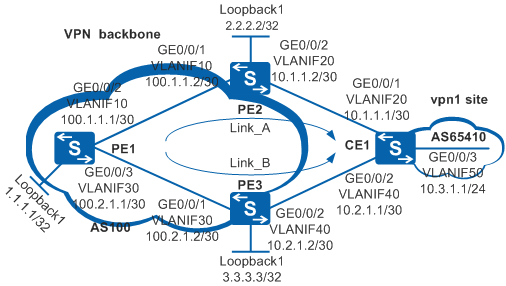
As shown in Figure 1, you need to configure the backup next hop on PE1 to make PE3 a backup of PE2. When a fault occurs on PE2, traffic can be quickly switched to PE3.

In this scenario, to avoid loops, ensure that all connected interfaces have STP disabled and connected interfaces are removed from VLAN 1. If STP is enabled and VLANIF interfaces of switches are used to construct a Layer 3 ring network, an interface on the network will be blocked. As a result, Layer 3 services on the network cannot run normally.
Configuration Roadmap
The configuration roadmap is as follows:
Configure OSPF on PE1, PE2, and PE3 to implement interworking on the backbone network.
Configure basic MPLS capabilities and MPLS LDP on the MPLS backbone network to establish LDP LSPs.
Configure a VPN instance on PE1, PE2, and PE3. Bind the interfaces connected to CE1 to the VPN instances on PE2 and PE3.
Establish EBGP peer relationships between PEs and CE1. Establish an MP-IBGP peer relationship between PEs.
On PE1, configure a routing policy for VPN FRR, configure the backup next hop, and enable VPN FRR. When VPN FRR is not required, run the undo vpn frr command to disable this function.
Configure the backup next hop on PE1 to make PE3 a backup of PE2. When a fault occurs on PE2, traffic can be quickly switched to PE3.
Procedure
- Configure VLANs on interfaces and assign IP addresses to the VLANIF interfaces and loopback interfaces according to Figure 1.
# Configure PE1. The configuration on PE2, PE3, and CE1 is similar to the configuration on PE1 and is not mentioned here.
<HUAWEI> system-view
[HUAWEI] sysname PE1
[PE1] interface loopback 1
[PE1-LoopBack1] ip address 1.1.1.1 32
[PE1-LoopBack1] quit
[PE1] vlan batch 10 30
[PE1] interface gigabitethernet 0/0/2
[PE1-GigabitEthernet0/0/2] port link-type trunk
[PE1-GigabitEthernet0/0/2] port trunk allow-pass vlan 10
[PE1-GigabitEthernet0/0/2] quit
[PE1] interface gigabitethernet 0/0/3
[PE1-GigabitEthernet0/0/3] port link-type trunk
[PE1-GigabitEthernet0/0/3] port trunk allow-pass vlan 30
[PE1-GigabitEthernet0/0/3] quit
[PE1] interface vlanif 10
[PE1-Vlanif10] ip address 100.1.1.1 30
[PE1-Vlanif10] quit
[PE1] interface vlanif 30
[PE1-Vlanif30] ip address 100.2.1.1 30
[PE1-Vlanif30] quit
- Configure OSPF on the MPLS backbone network for IP connectivity between the PEs on the backbone network.
# Configure PE1. The configuration on PE2 and PE3 is similar to the configuration on PE1 and is not mentioned here.
[PE1] ospf
[PE1-ospf-1] area 0
[PE1-ospf-1-area-0.0.0.0] network 100.1.1.0 0.0.0.3
[PE1-ospf-1-area-0.0.0.0] network 100.2.1.0 0.0.0.3
[PE1-ospf-1-area-0.0.0.0] network 1.1.1.1 0.0.0.0
[PE1-ospf-1-area-0.0.0.0] quit
[PE1-ospf-1] quit
- Configure basic MPLS capabilities and MPLS LDP on the MPLS backbone network to establish LDP LSPs.
# Configure PE1.
[PE1] mpls lsr-id 1.1.1.1
[PE1] mpls
[PE1-mpls] label advertise non-null
[PE1-mpls] quit
[PE1] mpls ldp
[PE1-mpls-ldp] quit
[PE1] interface vlanif 10
[PE1-Vlanif10] mpls
[PE1-Vlanif10] mpls ldp
[PE1-Vlanif10] quit
[PE1] interface vlanif 30
[PE1-Vlanif30] mpls
[PE1-Vlanif30] mpls ldp
[PE1-Vlanif30] quit
# Configure PE2.
[PE2] mpls lsr-id 2.2.2.2
[PE2] mpls
[PE2-mpls] label advertise non-null
[PE2-mpls] quit
[PE2] mpls ldp
[PE2-mpls-ldp] quit
[PE2] interface vlanif 10
[PE2-Vlanif10] mpls
[PE2-Vlanif10] mpls ldp
[PE2-Vlanif10] quit
# Configure PE3.
[PE3] mpls lsr-id 3.3.3.3
[PE3] mpls
[PE3-mpls] label advertise non-null
[PE3-mpls] quit
[PE3] mpls ldp
[PE3-mpls-ldp] quit
[PE3] interface vlanif 30
[PE3-Vlanif30] mpls
[PE3-Vlanif30] mpls ldp
[PE3-Vlanif30] quit
Run the display mpls lsp command on the PEs. The command output shows that LSPs are established between PE1 and PE2 and between PE1 and PE3. The information displayed on PE1 is used as an example.
[PE1] display mpls lsp Flag after Out IF: (I) - LSP Is Only Iterated by RLFA ------------------------------------------------------------------------------- LSP Information: LDP LSP ------------------------------------------------------------------------------- FEC In/Out Label In/Out IF Vrf Name 1.1.1.1/32 1024/NULL -/- 2.2.2.2/32 NULL/1025 -/Vlanif10 2.2.2.2/32 1025/1025 -/Vlanif10 3.3.3.3/32 NULL/1026 -/Vlanif30 3.3.3.3/32 1026/1026 -/Vlanif30 - Configure VPN instances on PEs and bind the interfaces connected to CEs to the VPN instances.
# Configure PE1.
[PE1] ip vpn-instance vpn1
[PE1-vpn-instance-vpn1] ipv4-family
[PE1-vpn-instance-vpn1-af-ipv4] route-distinguisher 100:1
[PE1-vpn-instance-vpn1-af-ipv4] vpn-target 111:1
[PE1-vpn-instance-vpn1-af-ipv4] quit
[PE1-vpn-instance-vpn1] quit
# Configure PE2.
[PE2] ip vpn-instance vpn1
[PE2-vpn-instance-vpn1] ipv4-family
[PE2-vpn-instance-vpn1-af-ipv4] route-distinguisher 100:2
[PE2-vpn-instance-vpn1-af-ipv4] vpn-target 111:1
[PE2-vpn-instance-vpn1-af-ipv4] quit
[PE2-vpn-instance-vpn1] quit
[PE2] interface vlanif 20
[PE2-Vlanif20] ip binding vpn-instance vpn1
[PE2-Vlanif20] ip address 10.1.1.2 30
[PE2-Vlanif20] quit
# Configure PE3.
[PE3] ip vpn-instance vpn1
[PE3-vpn-instance-vpn1] ipv4-family
[PE3-vpn-instance-vpn1-af-ipv4] route-distinguisher 100:3
[PE3-vpn-instance-vpn1-af-ipv4] vpn-target 111:1
[PE3-vpn-instance-vpn1-af-ipv4] quit
[PE3-vpn-instance-vpn1] quit
[PE3] interface vlanif 40
[PE3-Vlanif40] ip binding vpn-instance vpn1
[PE3-Vlanif40] ip address 10.2.1.2 30
[PE3-Vlanif40] quit
- Import direct VPN routes to PE1. Establish EBGP peer relationships between PE2 and CE1 and between PE3 and CE1 to import VPN routes.
# Configure PE1.
[PE1] bgp 100
[PE1-bgp] ipv4-family vpn-instance vpn1
[PE1-bgp-vpn1] import-route direct
[PE1-bgp-vpn1] quit
[PE1-bgp] quit
# Configure PE2.
[PE2] bgp 100
[PE2-bgp] ipv4-family vpn-instance vpn1
[PE2-bgp-vpn1] peer 10.1.1.1 as-number 65410
[PE2-bgp-vpn1] import-route direct
[PE2-bgp-vpn1] quit
[PE2-bgp] quit
# Configure PE3.
[PE3] bgp 100
[PE3-bgp] ipv4-family vpn-instance vpn1
[PE3-bgp-vpn1] peer 10.2.1.1 as-number 65410
[PE3-bgp-vpn1] import-route direct
[PE3-bgp-vpn1] quit
[PE3-bgp] quit
# Configure CE1.
[CE1] bgp 65410
[CE1-bgp] peer 10.1.1.2 as-number 100
[CE1-bgp] peer 10.2.1.2 as-number 100
[CE1-bgp] import-route direct
[CE1-bgp] network 10.3.1.0 24
[CE1-bgp] quit
Run the display bgp vpnv4 all peer command on PE2 and PE3. The command output shows that EBGP peer relationships have been established between PE2 and CE1 and between PE3 and CE1, and are in Established state.
The information displayed on PE2 is used as an example.
[PE2] display bgp vpnv4 all peer

 BGP local router ID : 2.2.2.2
 Local AS number : 100
 Total number of peers : 1                 Peers in established state : 1

  Peer            V          AS  MsgRcvd  MsgSent  OutQ  Up/Down       State PrefRcv


  Peer of IPv4-family for vpn instance :

 VPN-Instance vpn1, Router ID 2.2.2.2:
  10.1.1.1        4       65410        1        1     0 00:00:57     Established   1
- Establish an MP-IBGP peer relationship between PEs.
# Configure PE1.
[PE1] bgp 100
[PE1-bgp] peer 2.2.2.2 as-number 100
[PE1-bgp] peer 2.2.2.2 connect-interface loopback 1
[PE1-bgp] peer 3.3.3.3 as-number 100
[PE1-bgp] peer 3.3.3.3 connect-interface loopback 1
[PE1-bgp] ipv4-family vpnv4
[PE1-bgp-af-vpnv4] peer 2.2.2.2 enable
[PE1-bgp-af-vpnv4] peer 3.3.3.3 enable
[PE1-bgp-af-vpnv4] quit
[PE1-bgp] quit
# Configure PE2.
[PE2] bgp 100
[PE2-bgp] peer 1.1.1.1 as-number 100
[PE2-bgp] peer 1.1.1.1 connect-interface loopback 1
[PE2-bgp] ipv4-family vpnv4
[PE2-bgp-af-vpnv4] peer 1.1.1.1 enable
[PE2-bgp-af-vpnv4] quit
[PE2-bgp] quit
# Configure PE3.
[PE3] bgp 100
[PE3-bgp] peer 1.1.1.1 as-number 100
[PE3-bgp] peer 1.1.1.1 connect-interface loopback 1
[PE3-bgp] ipv4-family vpnv4
[PE3-bgp-af-vpnv4] peer 1.1.1.1 enable
[PE3-bgp-af-vpnv4] quit
[PE3-bgp] quit
Run the display bgp vpnv4 all peer command on the PEs. The command output shows that an MP-IBGP peer relationship has been established between the PEs and is in Established state.
The information displayed on PE1 is used as an example.
[PE1] display bgp vpnv4 all peer

 BGP local router ID : 1.1.1.1
 Local AS number : 100
 Total number of peers : 2                 Peers in established state : 2

  Peer            V          AS  MsgRcvd  MsgSent  OutQ  Up/Down       State PrefRcv

  2.2.2.2         4         100        3        4     0 00:00:26 Established       1
  3.3.3.3         4         100        5        4     0 00:00:24 Established       4
- Configure the VPN FRR routing policy.
[PE1] ip ip-prefix vpn_frr_list permit 2.2.2.2 32
[PE1] route-policy vpn_frr_rp permit node 10
[PE1-route-policy] if-match ip next-hop ip-prefix vpn_frr_list
[PE1-route-policy] apply backup-nexthop 3.3.3.3
[PE1-route-policy] quit
- Enable VPN FRR.
[PE1] ip vpn-instance vpn1
[PE1-vpn-instance-vpn1] vpn frr route-policy vpn_frr_rp
[PE1-vpn-instance-vpn1] quit
# Check the backup next hop, backup label, and backup tunnel ID.
[PE1] display ip routing-table vpn-instance vpn1 10.3.1.0 verbose
Route Flags: R - relay, D - download to fib, T - to vpn-instance
------------------------------------------------------------------------------
Routing Table : vpn1
Summary Count : 1

Destination: 10.3.1.0/24
     Protocol: IBGP             Process ID: 0
   Preference: 255                    Cost: 0
      NextHop: 2.2.2.2           Neighbour: 2.2.2.2
        State: Active Adv Relied       Age: 00h00m56s
          Tag: 0                  Priority: low
        Label: 1026                QoSInfo: 0x0
   IndirectID: 0x1b
 RelayNextHop: 100.1.1.2         Interface: Vlanif10
     TunnelID: 0x4800009a            Flags: RD
    BkNextHop: 3.3.3.3         BkInterface: Vlanif30
      BkLabel: 1027            SecTunnelID: 0x0
 BkPETunnelID: 0x4800009c  BkPESecTunnelID: 0x0
 BkIndirectID: 0x1e
In this example, both PE2 and PE3 advertise the route 10.3.1.0/24 with the same BGP attribute to PE1. The router ID of PE2 is smaller than that of PE3 so that PE1 preferentially selects the route advertised by PE2, that is, Link_A. If the router ID of PE2 is greater than that of PE3 in a real-world situation, PE1 preferentially selects the route advertised by PE2, that is, Link_B. In this case, VPN FRR fails if the preceding configurations are followed. To prevent the problem from occurring, you can modify VPNv4 route attributes in the BGP-VPNv4 address family view, ensuring that PE1 preferentially selecting Link_A. There are many methods to modify VPNv4 route attributes. The following part shows the most common two methods:- In the BGP-VPNv4 address family view of PE1, set a higher PrefVal for the routes learnt from PE2. The relevant configuration is as follows:
route-policy policy1 permit node 10
 apply preferred-value 100
#
bgp 100
 #
 ipv4-family vpnv4
  peer 2.2.2.2 route-policy policy1 import
- In the BGP-VPNv4 address family view of PE2, set a higher Local_Pref for the advertised routes. The relevant configuration is as follows:
route-policy policy2 permit node 10
 apply local-preference 200
#
bgp 100
 #
 ipv4-family vpnv4
  peer 1.1.1.1 route-policy policy2 export
- In the BGP-VPNv4 address family view of PE1, set a higher PrefVal for the routes learnt from PE2. The relevant configuration is as follows:
Configuration Files
PE1 configuration file
#
sysname PE1
#
vlan batch 10 30
#
ip vpn-instance vpn1
 ipv4-family
  route-distinguisher 100:1
  vpn frr route-policy vpn_frr_rp
  vpn-target 111:1 export-extcommunity
  vpn-target 111:1 import-extcommunity
#
mpls lsr-id 1.1.1.1
mpls
 label advertise non-null
#
mpls ldp
#
interface Vlanif10
 ip address 100.1.1.1 255.255.255.252
 mpls
 mpls ldp
#
interface Vlanif30
 ip address 100.2.1.1 255.255.255.252
 mpls
 mpls ldp
#
interface GigabitEthernet0/0/2
 port link-type trunk
 port trunk allow-pass vlan 10
#
interface GigabitEthernet0/0/3
 port link-type trunk
 port trunk allow-pass vlan 30
#
interface LoopBack1
 ip address 1.1.1.1 255.255.255.255
#
bgp 100
 peer 2.2.2.2 as-number 100
 peer 2.2.2.2 connect-interface LoopBack1
 peer 3.3.3.3 as-number 100
 peer 3.3.3.3 connect-interface LoopBack1
 #
 ipv4-family unicast
  undo synchronization
  peer 2.2.2.2 enable
  peer 3.3.3.3 enable
 #
 ipv4-family vpnv4
  policy vpn-target
  peer 2.2.2.2 enable
  peer 3.3.3.3 enable
 #
 ipv4-family vpn-instance vpn1
  import-route direct
#
ospf 1
 area 0.0.0.0
  network 1.1.1.1 0.0.0.0
  network 100.1.1.0 0.0.0.3
  network 100.2.1.0 0.0.0.3
#
route-policy vpn_frr_rp permit node 10
 if-match ip next-hop ip-prefix vpn_frr_list
 apply backup-nexthop 3.3.3.3
#
ip ip-prefix vpn_frr_list index 10 permit 2.2.2.2 32
#
return
PE2 configuration file
#
sysname PE2
#
vlan batch 10 20
#
ip vpn-instance vpn1
 ipv4-family
  route-distinguisher 100:2
  vpn-target 111:1 export-extcommunity
  vpn-target 111:1 import-extcommunity
#
mpls lsr-id 2.2.2.2
mpls
 label advertise non-null
#
mpls ldp
#
interface Vlanif10
 ip address 100.1.1.2 255.255.255.252
 mpls
 mpls ldp
#
interface Vlanif20
 ip binding vpn-instance vpn1
 ip address 10.1.1.2 255.255.255.252
#
interface GigabitEthernet0/0/1
 port link-type trunk
 port trunk allow-pass vlan 10
#
interface GigabitEthernet0/0/2
 port link-type trunk
 port trunk allow-pass vlan 20
#
interface LoopBack1
 ip address 2.2.2.2 255.255.255.255
#
bgp 100
 peer 1.1.1.1 as-number 100
 peer 1.1.1.1 connect-interface LoopBack1
 #
 ipv4-family unicast
  undo synchronization
  peer 1.1.1.1 enable
 #
 ipv4-family vpnv4
  policy vpn-target
  peer 1.1.1.1 enable
 #
 ipv4-family vpn-instance vpn1
  import-route direct
  peer 10.1.1.1 as-number 65410
#
ospf 1
 area 0.0.0.0
  network 2.2.2.2 0.0.0.0
  network 100.1.1.0 0.0.0.3
#
return
PE3 configuration file
#
sysname PE3
#
vlan batch 30 40
#
ip vpn-instance vpn1
 ipv4-family
  route-distinguisher 100:3
  vpn-target 111:1 export-extcommunity
  vpn-target 111:1 import-extcommunity
#
mpls lsr-id 3.3.3.3
mpls
 label advertise non-null
#
mpls ldp
#
interface Vlanif30
 ip address 100.2.1.2 255.255.255.252
 mpls
 mpls ldp
#
interface Vlanif40
 ip binding vpn-instance vpn1
 ip address 10.2.1.2 255.255.255.252
#
interface GigabitEthernet0/0/1
 port link-type trunk
 port trunk allow-pass vlan 30
#
interface GigabitEthernet0/0/2
 port link-type trunk
 port trunk allow-pass vlan 40
#
interface LoopBack1
 ip address 3.3.3.3 255.255.255.255
#
bgp 100
 peer 1.1.1.1 as-number 100
 peer 1.1.1.1 connect-interface LoopBack1
 #
 ipv4-family unicast
  undo synchronization
  peer 1.1.1.1 enable
 #
 ipv4-family vpnv4
  policy vpn-target
  peer 1.1.1.1 enable
 #
 ipv4-family vpn-instance vpn1
  import-route direct
  peer 10.2.1.1 as-number 65410
#
ospf 1
 area 0.0.0.0
  network 3.3.3.3 0.0.0.0
  network 100.2.1.0 0.0.0.3
#
return
CE1 configuration file
#
sysname CE1
#
vlan batch 20 40 50
#
interface Vlanif20
 ip address 10.1.1.1 255.255.255.252
#
interface Vlanif40
 ip address 10.2.1.1 255.255.255.252
#
interface Vlanif50
 ip address 10.3.1.1 255.255.255.0
#
interface GigabitEthernet0/0/1
 port link-type trunk
 port trunk allow-pass vlan 20
#
interface GigabitEthernet0/0/2
 port link-type trunk
 port trunk allow-pass vlan 40
#
interface GigabitEthernet0/0/3
 port link-type trunk
 port trunk allow-pass vlan 50
#
bgp 65410
 peer 10.1.1.2 as-number 100
 peer 10.2.1.2 as-number 100
 #
 ipv4-family unicast
  undo synchronization
  network 10.3.1.0 255.255.255.0
  import-route direct
  peer 10.1.1.2 enable
  peer 10.2.1.2 enable
#
return