Example for Configuring IP FRR for VPN Routes
Networking Requirements
When multiple CEs in a site connect to the same PE, the PE learns multiple IP VPN routes with the same VPN prefix. To use one of IP VPN routes as the primary route and the other as backup routes, configure IP FRR for VPN routes. Then the PE generates primary and backup routes to the VPN prefix. When the link of the primary route fails, IP traffic on the VPN is quickly switched to the link of a backup route.
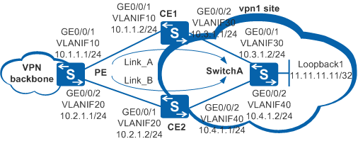
As shown in Figure 1, the PE has two OSPF routes to Loopback1 of SwitchA. The route on Link_A is the optimal route, and the route on Link_B is the suboptimal route. IP FRR for VPN routes needs to be configured on the PE to quickly switch IP traffic on the VPN to Link_B when Link_A fails.

In this scenario, to avoid loops, ensure that all connected interfaces have STP disabled and connected interfaces are removed from VLAN 1. If STP is enabled and VLANIF interfaces of switches are used to construct a Layer 3 ring network, an interface on the network will be blocked. As a result, Layer 3 services on the network cannot run normally.
Configuration Roadmap
The configuration roadmap is as follows:
Configure OSPF in the VPN sites so that the routes to the loopback interface of SwitchA can be advertised to CE1 and CE2.
Configure VPN instance vpna on the PE and bind the interfaces connected to CE1 and CE2 to vpna.
Set the cost on vlanif of the PE and RTA both to a large value so that OSPF preferentially selects Link_A.
Configure IP FRR for VPN routes on the PE.
Configure BFD to detect the link status.
Procedure
- Configure IP addresses for interfaces on the devices in
the VPN site.
# Configure SwitchA. The configuration on PE, CE1, and CE2 is similar to the configuration on SwitchA and is not mentioned here.
<HUAWEI> system-view
[HUAWEI] sysname SwitchA
[SwitchA] interface loopback 1
[SwitchA-LoopBack1] ip address 11.11.11.11 32
[SwitchA-LoopBack1] quit
[SwitchA] vlan batch 30 40
[SwitchA] interface gigabitethernet 0/0/1
[SwitchA-GigabitEthernet0/0/1] port link-type trunk
[SwitchA-GigabitEthernet0/0/1] port trunk allow-pass vlan 30
[SwitchA-GigabitEthernet0/0/1] quit
[SwitchA] interface gigabitethernet 0/0/2
[SwitchA-GigabitEthernet0/0/2] port link-type trunk
[SwitchA-GigabitEthernet0/0/2] port trunk allow-pass vlan 40
[SwitchA-GigabitEthernet0/0/2] quit
[SwitchA] interface vlanif 30
[SwitchA-Vlanif30] ip address 10.3.1.2 24
[SwitchA-Vlanif30] quit
[SwitchA] interface vlanif 40
[SwitchA-Vlanif40] ip address 10.4.1.2 24
[SwitchA-Vlanif40] quit
- Configure an IGP in the VPN site so that the routes to
the loopback interface of SwitchA can be advertised to CE1 and CE2. OSPF is used in this example.
# Configure CE1. The configuration on CE2 and SwitchA is similar to the configuration on CE1 and is not mentioned here.
[CE1] ospf 1
[CE1-ospf-1] area 0
[CE1-ospf-1-area-0.0.0.0] network 10.1.1.0 0.0.0.255
[CE1-ospf-1-area-0.0.0.0] network 10.3.1.0 0.0.0.255
[CE1-ospf-1-area-0.0.0.0] quit
[CE1-ospf-1] quit
After the configuration is complete, run the display ip routing-table command on CE1 and CE2. You can see that CE1 and CE2 have learned the routes to Loopback1 of SwitchA.
- Configure a VPN instance on the PE and bind interfaces
connected to CEs to the VPN instance.
# Configure VPN instance vpna on the PE and bind VLANIF10 and VLANIF20 to vpna.
[PE] ip vpn-instance vpna
[PE-vpn-instance-vpna] ipv4-family
[PE-vpn-instance-vpna-af-ipv4] route-distinguisher 100:1
[PE-vpn-instance-vpna-af-ipv4] vpn-target 100:100
[PE-vpn-instance-vpna-af-ipv4] quit
[PE-vpn-instance-vpna] quit
[PE] interface vlanif 10
[PE-Vlanif10] ip binding vpn-instance vpna
[PE-Vlanif10] ip address 10.1.1.1 24
[PE-Vlanif10] quit
[PE] interface vlanif 20
[PE-Vlanif20] ip binding vpn-instance vpna
[PE-Vlanif20] ip address 10.2.1.1 24
[PE-Vlanif20] quit
# Configure OSPF multi-instance on the PE.
[PE] ospf vpn-instance vpna
[PE-ospf-1] area 0
[PE-ospf-1-area-0.0.0.0] network 10.1.1.0 0.0.0.255
[PE-ospf-1-area-0.0.0.0] network 10.2.1.0 0.0.0.255
[PE-ospf-1-area-0.0.0.0] quit
[PE-ospf-1] quit
- Set the cost on the OSPF interface.
# Set the cost on vlanif20 of the PE to 100 so that OSPF preferentially selects Link_A.
[PE] interface vlanif 20
[PE-Vlanif20] ospf cost 100
[PE-Vlanif20] quit
# Set the cost on vlanif40 of SwitchA to 100 so that OSPF preferentially selects Link_A.
[SwitchA] interface vlanif 40
[SwitchA-Vlanif40] ospf cost 100
[SwitchA-Vlanif40] quit
- Configure a routing policy.
# Configure a routing policy, a backup next hop, and a backup outbound interface on the PE. Configure an if-match clause.
[PE] ip ip-prefix frr1 permit 11.11.11.11 32
[PE] route-policy ip_frr_rp permit node 10
[PE-route-policy] if-match ip-prefix frr1
[PE-route-policy] apply backup-nexthop 10.2.1.2
[PE-route-policy] apply backup-interface vlanif 20
[PE-route-policy] quit
- Configure association between BFD and IP FRR.
# Configure the PE.
[PE] bfd
[PE-bfd] quit
[PE] bfd for_ip_frr bind peer-ip 10.1.1.2 vpn-instance vpna interface vlanif 10
[PE-bfd-session-for_ip_frr] discriminator local 10
[PE-bfd-session-for_ip_frr] discriminator remote 20
[PE-bfd-session-for_ip_frr] commit
[PE-bfd-session-for_ip_frr] quit
# Configure CE1.
[CE1] bfd
[CE1-bfd] quit
[CE1] bfd for_ip_frr bind peer-ip 10.1.1.1 interface vlanif 10
[CE1-bfd-session-for_ip_frr] discriminator local 20
[CE1-bfd-session-for_ip_frr] discriminator remote 10
[CE1-bfd-session-for_ip_frr] commit
[CE1-bfd-session-for_ip_frr] quit
# Run the display bfd session all verbose command on the PE and CE1. The command output shows that the BFD session status is Up.
- Enable IP FRR for VPN routes.
[PE] ip vpn-instance vpna
[PE-vpn-instance-vpna] ipv4-family
[PE-vpn-instance-vpna-af-ipv4] ip frr route-policy ip_frr_rp
[PE-vpn-instance-vpna-af-ipv4] quit
[PE-vpn-instance-vpna] quit
- Verify the configurations.
Run the display ip routing-table vpn-instance command on the PE. The command output shows that the next hop of the route to 11.11.11.11/32 is 10.1.1.2, and the route has a backup next hop and a backup outbound interface.
[PE] display ip routing-table vpn-instance vpna 11.11.11.11 verbose
Route Flags: R - relay, D - download to fib, T - to vpn-instance
------------------------------------------------------------------------------
Routing Table : vpna
Summary Count : 1

Destination: 11.11.11.11/32
     Protocol: OSPF            Process ID: 1
   Preference: 10                    Cost: 3
      NextHop: 10.1.1.2         Neighbour: 0.0.0.0
        State: Active Adv             Age: 00h00m03s
          Tag: 0                 Priority: high
        Label: NULL               QoSInfo: 0x0
   IndirectID: 0x0
 RelayNextHop: 0.0.0.0          Interface: Vlanif10
     TunnelID: 0x0                  Flags: D
    BkNextHop: 10.2.1.2       BkInterface: Vlanif20
      BkLabel: NULL           SecTunnelID: 0x0
 BkPETunnelID: 0x0        BkPESecTunnelID: 0x0
 BkIndirectID: 0x0
Run the shutdown command on GigabitEthernet0/0/2 of CE1 to simulate a link failure.
[CE1] interface gigabitethernet 0/0/2
[CE1-GigabitEthernet0/0/2] shutdown
[CE1-GigabitEthernet0/0/2] quit
Run the display ip routing-table vpn-instance command on the PE. The command output shows that the next hop of the route to 11.11.11.11/32 is 10.2.1.2, and the route has no backup next hop or backup outbound interface.
[PE] display ip routing-table vpn-instance vpna 11.11.11.11 verbose
Route Flags: R - relay, D - download to fib, T - to vpn-instance
------------------------------------------------------------------------------
Routing Table : vpna
Summary Count : 1

Destination: 11.11.11.11/32
     Protocol: OSPF             Process ID: 1
   Preference: 10                     Cost: 101
      NextHop: 10.2.1.2          Neighbour: 0.0.0.0
        State: Active Adv              Age: 00h01m42s
          Tag: 0                  Priority: high
        Label: NULL                QoSInfo: 0x0
   IndirectID: 0x0
 RelayNextHop: 0.0.0.0           Interface: Vlanif20
     TunnelID: 0x0                   Flags:  D
    BkNextHop: 10.2.1.2        BkInterface: Vlanif20
      BkLabel: NULL            SecTunnelID: 0x0
 BkPETunnelID: 0x0         BkPESecTunnelID: 0x0
 BkIndirectID: 0x0
This indicates that IP FRR for VPN routes has taken effect.
Configuration Files
- PE configuration file
#
sysname PE
#
vlan batch 10 20
#
ip vpn-instance vpna
 ipv4-family
  route-distinguisher 100:1
  ip frr route-policy ip_frr_rp
  vpn-target 100:100 export-extcommunity
  vpn-target 100:100 import-extcommunity
#
bfd
#
interface Vlanif10
 ip binding vpn-instance vpna
 ip address 10.1.1.1 255.255.255.0
#
interface Vlanif20
 ip binding vpn-instance vpna
 ip address 10.2.1.1 255.255.255.0
 ospf cost 100
#
interface GigabitEthernet0/0/1
 port link-type trunk
 port trunk allow-pass vlan 10
#
interface GigabitEthernet0/0/2
 port link-type trunk
 port trunk allow-pass vlan 20
#
bfd for_ip_frr bind peer-ip 10.1.1.2 vpn-instance vpna interface Vlanif10
 discriminator local 10
 discriminator remote 20
 commit
#
ospf 1 vpn-instance vpna
 area 0.0.0.0
  network 10.1.1.0 0.0.0.255
  network 10.2.1.0 0.0.0.255
#
route-policy ip_frr_rp permit node 10
 if-match ip-prefix frr1
 apply backup-nexthop 10.2.1.2
 apply backup-interface Vlanif20
#
ip ip-prefix frr1 index 10 permit 11.11.11.11 32
#
return
- CE1 configuration file
#
sysname CE1
#
vlan batch 10 30
#
bfd
#
interface Vlanif10
 ip address 10.1.1.2 255.255.255.0
#
interface Vlanif30
 ip address 10.3.1.1 255.255.255.0
#
interface GigabitEthernet0/0/1
 port link-type trunk
 port trunk allow-pass vlan 10
#
interface GigabitEthernet0/0/2
 port link-type trunk
 port trunk allow-pass vlan 30
#
bfd for_ip_frr bind peer-ip 10.1.1.1 interface Vlanif10
 discriminator local 20
 discriminator remote 10
 commit
#
ospf 1
 area 0.0.0.0
  network 10.1.1.0 0.0.0.255
  network 10.3.1.0 0.0.0.255
#
return
- CE2 configuration file
#
sysname CE2
#
vlan batch 20 40
#
interface Vlanif20
 ip address 10.2.1.2 255.255.255.0
#
interface Vlanif40
 ip address 10.4.1.1 255.255.255.0
#
interface GigabitEthernet0/0/1
 port link-type trunk
 port trunk allow-pass vlan 20
#
interface GigabitEthernet0/0/2
 port link-type trunk
 port trunk allow-pass vlan 40
#
ospf 1
 area 0.0.0.0
  network 10.2.1.0 0.0.0.255
  network 10.4.1.0 0.0.0.255
#
return
- SwitchA configuration
file
#
sysname SwitchA
#
vlan batch 30 40
#
interface Vlanif30
 ip address 10.3.1.2 255.255.255.0
#
interface Vlanif40
 ip address 10.4.1.2 255.255.255.0
 ospf cost 100
#
interface GigabitEthernet0/0/1
 port link-type trunk
 port trunk allow-pass vlan 30
#
interface GigabitEthernet0/0/2
 port link-type trunk
 port trunk allow-pass vlan 40
#
interface LoopBack1
 ip address 11.11.11.11 255.255.255.255
#
ospf 1
 area 0.0.0.0
  network 10.3.1.0 0.0.0.255
  network 10.4.1.0 0.0.0.255
  network 11.11.11.11 0.0.0.0
#
return