Example for Configuring a Tunnel Policy for an L3VPN
Networking Requirements
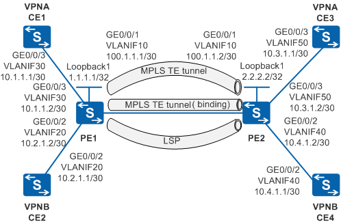
Figure 1 shows the MPLS L3VPN networking. CE1 and CE3 belong to VPNA, and CE2 and CE4 belongs to VPNB. Two MPLS TE tunnels and one LSP are established between PE1 and PE2. VPNA is bound to a TE tunnel, and VPNB prefers a TE tunnel for loading balance.
Configuration Roadmap
The configuration roadmap is as follows:
Configure a routing protocol so that PEs can communicate with each other.
Configure basic MPLS capabilities on the PEs on the backbone network and establish an LSP and two MPLS TE tunnels between the PEs.
Configure VPN instances on PEs and bind the interfaces connected to CEs to the VPN instances.
Configure tunnel policies and apply the policies to different VPN instances.
Configure MP-IBGP to exchange VPN routing information.
Procedure
- Configure an IGP on the MPLS backbone network so that PEs
can communicate.
# Configure PE1.
<HUAWEI> system-view
[HUAWEI] sysname PE1
[PE1] interface loopback 1
[PE1-LoopBack1] ip address 1.1.1.1 32
[PE1-LoopBack1] quit
[PE1] vlan 10
[PE1-vlan10] quit
[PE1] interface gigabitethernet 0/0/1
[PE1-GigabitEthernet0/0/1] port link-type trunk
[PE1-GigabitEthernet0/0/1] port trunk allow-pass vlan 10
[PE1-GigabitEthernet0/0/1] quit
[PE1] interface vlanif 10
[PE1-Vlanif10] ip address 100.1.1.1 30
[PE1-Vlanif10] quit
[PE1] ospf 1
[PE1-ospf-1] area 0
[PE1-ospf-1-area-0.0.0.0] network 100.1.1.0 0.0.0.3
[PE1-ospf-1-area-0.0.0.0] network 1.1.1.1 0.0.0.0
[PE1-ospf-1-area-0.0.0.0] quit
[PE1-ospf-1] quit
# Configure PE2.
<HUAWEI> system-view
[HUAWEI] sysname PE2
[PE2] interface loopback 1
[PE2-LoopBack1] ip address 2.2.2.2 32
[PE2-LoopBack1] quit
[PE2] vlan 10
[PE2-vlan10] quit
[PE2] interface gigabitethernet 0/0/1
[PE2-GigabitEthernet0/0/1] port link-type trunk
[PE2-GigabitEthernet0/0/1] port trunk allow-pass vlan 10
[PE2-GigabitEthernet0/0/1] quit
[PE2] interface vlanif 10
[PE2-Vlanif10] ip address 100.1.1.2 30
[PE2-Vlanif10] quit
[PE2] ospf 1
[PE2-ospf-1] area 0
[PE2-ospf-1-area-0.0.0.0] network 100.1.1.0 0.0.0.3
[PE2-ospf-1-area-0.0.0.0] network 2.2.2.2 0.0.0.0
[PE2-ospf-1-area-0.0.0.0] quit
[PE2-ospf-1] quit
# After the configuration is complete, run the display ip routing-table command on the PEs, and you can view that the PEs have learned the routes to Loopback1 interfaces from each other.
# The information displayed on PE1 is used as an example.
[PE1] display ip routing-table Route Flags: R - relay, D - download to fib, T - to vpn-instance ------------------------------------------------------------------------------ Routing Tables: Public Destinations : 6 Routes : 6 Destination/Mask Proto Pre Cost Flags NextHop Interface 1.1.1.1/32 Direct 0 0 D 127.0.0.1 LoopBack1 2.2.2.2/32 OSPF 10 1 D 100.1.1.2 Vlanif10 100.1.1.0/30 Direct 0 0 D 100.1.1.1 Vlanif10 100.1.1.1/32 Direct 0 0 D 127.0.0.1 Vlanif10 127.0.0.0/8 Direct 0 0 D 127.0.0.1 InLoopBack0 127.0.0.1/32 Direct 0 0 D 127.0.0.1 InLoopBack0 - Configure basic MPLS capabilities on the MPLS backbone
to establish an LDP LSP between PEs.
# Configure PE1.
[PE1] mpls lsr-id 1.1.1.1
[PE1] mpls
[PE1-mpls] label advertise non-null
[PE1-mpls] quit
[PE1] mpls ldp
[PE1-mpls-ldp] quit
[PE1] interface vlanif 10
[PE1-Vlanif10] mpls
[PE1-Vlanif10] mpls ldp
[PE1-Vlanif10] quit
# Configure PE2.
[PE2] mpls lsr-id 2.2.2.2
[PE2] mpls
[PE2-mpls] label advertise non-null
[PE2-mpls] quit
[PE2] mpls ldp
[PE2-mpls-ldp] quit
[PE2] interface vlanif 10
[PE2-Vlanif10] mpls
[PE2-Vlanif10] mpls ldp
[PE2-Vlanif10] quit
# After the configuration is complete, an LDP LSP is established between PE1 and PE2. Run the display tunnel-info all command, and you can find the LSP destined for the address 2.2.2.2. Run the display mpls ldp lsp command, and you can view LSP information.
# The information displayed on PE1 is used as an example.
[PE1] display tunnel-info all
 * -> Allocated VC Token
Tunnel ID           Type                 Destination           Token
----------------------------------------------------------------------
0x1                 lsp                   2.2.2.2                1
0x2                 lsp                   2.2.2.2                2
[PE1] display mpls ldp lsp LDP LSP Information ------------------------------------------------------------------------------- Flag after Out IF: (I) - LSP Is Only Iterated by RLFA ------------------------------------------------------------------------------- DestAddress/Mask In/OutLabel UpstreamPeer NextHop OutInterface ------------------------------------------------------------------------------- 1.1.1.1/32 1026/NULL 2.2.2.2 127.0.0.1 InLoop0 *1.1.1.1/32 Liberal/1026 DS/2.2.2.2 2.2.2.2/32 NULL/1024 - 100.1.1.2 Vlanif10 2.2.2.2/32 1024/1024 2.2.2.2 100.1.1.2 Vlanif10 ------------------------------------------------------------------------------- TOTAL: 3 Normal LSP(s) Found. TOTAL: 1 Liberal LSP(s) Found. TOTAL: 0 Frr LSP(s) Found. A '*' before an LSP means the LSP is not established A '*' before a Label means the USCB or DSCB is stale A '*' before a UpstreamPeer means the session is stale A '*' before a DS means the session is stale A '*' before a NextHop means the LSP is FRR LSP - Establish MPLS TE tunnels between PEs.
# Configure PE1.
[PE1] mpls
[PE1-mpls] mpls te
[PE1-mpls] mpls rsvp-te
[PE1-mpls] mpls te cspf
[PE1-mpls] quit
[PE1] interface tunnel 1
[PE1-Tunnel1] ip address unnumbered interface loopback 1
[PE1-Tunnel1] tunnel-protocol mpls te
[PE1-Tunnel1] destination 2.2.2.2
[PE1-Tunnel1] mpls te tunnel-id 11
[PE1-Tunnel1] mpls te commit
[PE1-Tunnel1] quit
[PE1] interface tunnel 2
[PE1-Tunnel2] ip address unnumbered interface loopback 1
[PE1-Tunnel2] tunnel-protocol mpls te
[PE1-Tunnel2] destination 2.2.2.2
[PE1-Tunnel2] mpls te tunnel-id 22
[PE1-Tunnel2] mpls te reserved-for-binding
[PE1-Tunnel2] mpls te commit
[PE1-Tunnel2] quit
[PE1] interface vlanif 10
[PE1-Vlanif10] mpls te
[PE1-Vlanif10] mpls rsvp-te
[PE1-Vlanif10] quit
# Configure PE2.
[PE2] mpls
[PE2-mpls] mpls te
[PE2-mpls] mpls rsvp-te
[PE2-mpls] mpls te cspf
[PE2-mpls] quit
[PE2] interface tunnel 1
[PE2-Tunnel1] ip address unnumbered interface loopback 1
[PE2-Tunnel1] tunnel-protocol mpls te
[PE2-Tunnel1] destination 1.1.1.1
[PE2-Tunnel1] mpls te tunnel-id 11
[PE2-Tunnel1] mpls te commit
[PE2-Tunnel1] quit
[PE2] interface tunnel 2
[PE2-Tunnel2] ip address unnumbered interface loopback 1
[PE2-Tunnel2] tunnel-protocol mpls te
[PE2-Tunnel2] destination 1.1.1.1
[PE2-Tunnel2] mpls te tunnel-id 22
[PE2-Tunnel2] mpls te reserved-for-binding
[PE2-Tunnel2] mpls te commit
[PE2-Tunnel2] quit
[PE2] interface vlanif 10
[PE2-Vlanif10] mpls
[PE2-Vlanif10] mpls te
[PE2-Vlanif10] mpls rsvp-te
[PE2-Vlanif10] quit
# Enable OSPF on the devices along the TE tunnels to transmit TE attributes.
# Configure PE1.
[PE1] ospf 1
[PE1-ospf-1] opaque-capability enable
[PE1-ospf-1] area 0
[PE1-ospf-1-area-0.0.0.0] mpls-te enable
[PE1-ospf-1-area-0.0.0.0] quit
[PE1-ospf-1] quit
# Configure PE2.
[PE2] ospf 1
[PE2-ospf-1] opaque-capability enable
[PE2-ospf-1] area 0
[PE2-ospf-1-area-0.0.0.0] mpls-te enable
[PE2-ospf-1-area-0.0.0.0] quit
[PE2-ospf-1] quit
# After the configuration is complete, run the display tunnel-info all command on the PEs. The command output shows that Tunnel1 and Tunnel2 are both Up. Tunnel2 on PE1 is used as an example.
[PE1]display tunnel-info all
 * -> Allocated VC Token
Tunnel ID           Type                 Destination           Token
----------------------------------------------------------------------
0x3                 cr lsp                2.2.2.2                3
0x4                 cr lsp                2.2.2.2                4
0x5                 lsp                   2.2.2.2                5
0x6                 lsp                   2.2.2.2                6
0x7                 lsp                   2.2.2.2                7
0x8                 lsp                   2.2.2.2                8
- Configure VPN instances on PEs and bind the interfaces
connected to CEs to the VPN instances.
# Configure PE1.
[PE1] ip vpn-instance VPNA
[PE1-vpn-instance-VPNA] route-distinguisher 100:1
[PE1-vpn-instance-VPNA-af-ipv4] vpn-target 111:1 both
[PE1-vpn-instance-VPNA-af-ipv4] quit
[PE1-vpn-instance-VPNA] quit
[PE1] ip vpn-instance VPNB
[PE1-vpn-instance-VPNB] route-distinguisher 100:2
[PE1-vpn-instance-VPNB-af-ipv4] vpn-target 222:2 both
[PE1-vpn-instance-VPNB-af-ipv4] quit
[PE1-vpn-instance-VPNB] quit
[PE1] vlan batch 20 30
[PE1] interface vlanif 30
[PE1-Vlanif30] ip binding vpn-instance VPNA
[PE1-Vlanif30] ip address 10.1.1.2 30
[PE1-Vlanif30] quit
[PE1] interface vlanif 20
[PE1-Vlanif20] ip binding vpn-instance VPNB
[PE1-Vlanif20] ip address 10.2.1.2 30
[PE1-Vlanif20] quit
[PE1] interface gigabitethernet 0/0/2
[PE1-GigabitEthernet0/0/2] port link-type trunk
[PE1-GigabitEthernet0/0/2] port trunk allow-pass vlan 20
[PE1-GigabitEthernet0/0/2] quit
[PE1] interface gigabitethernet 0/0/3
[PE1-GigabitEthernet0/0/3] port link-type trunk
[PE1-GigabitEthernet0/0/3] port trunk allow-pass vlan 30
[PE1-GigabitEthernet0/0/3] quit
# Configure PE2.
[PE2] ip vpn-instance VPNA
[PE2-vpn-instance-VPNA] route-distinguisher 100:3
[PE2-vpn-instance-VPNA-af-ipv4] vpn-target 111:1 both
[PE2-vpn-instance-VPNA-af-ipv4] quit
[PE2-vpn-instance-VPNA] quit
[PE2] ip vpn-instance VPNB
[PE2-vpn-instance-VPNB] route-distinguisher 100:4
[PE2-vpn-instance-VPNB-af-ipv4] vpn-target 222:2 both
[PE2-vpn-instance-VPNB-af-ipv4] quit
[PE2-vpn-instance-VPNB] quit
[PE2] vlan batch 40 50
[PE2] interface vlanif 50
[PE2-Vlanif50] ip binding vpn-instance VPNA
[PE2-Vlanif50] ip address 10.3.1.2 30
[PE2-Vlanif50] quit
[PE2] interface vlanif 40
[PE2-Vlanif40] ip binding vpn-instance VPNB
[PE2-Vlanif40] ip address 10.4.1.2 30
[PE2-Vlanif40] quit
[PE2] interface gigabitethernet 0/0/2
[PE2-GigabitEthernet0/0/2] port link-type trunk
[PE2-GigabitEthernet0/0/2] port trunk allow-pass vlan 40
[PE2-GigabitEthernet0/0/2] quit
[PE2] interface gigabitethernet 0/0/3
[PE2-GigabitEthernet0/0/3] port link-type trunk
[PE2-GigabitEthernet0/0/3] port trunk allow-pass vlan 50
[PE2-GigabitEthernet0/0/3] quit
# Configure the interface addresses of the VLAN where the CE1 interface resides and configure the IP addresses of the VLANIF interfaces according to Figure 1. CE2, CE3 and CE4 is similar to the configuration on CE1 and is not mentioned here.
<HUAWEI> system-view
[HUAWEI] sysname CE1
[CE1] vlan batch 30
[CE1] interface gigabitethernet 0/0/3
[CE1-GigabitEthernet0/0/3] port link-type trunk
[CE1-GigabitEthernet0/0/3] port trunk allow-pass vlan 30
[CE1-GigabitEthernet0/0/3] quit
[CE1] interface vlanif 30
[CE1-Vlanif30] ip address 10.1.1.1 30
[CE1-Vlanif30] quit
# After the configuration is complete, run the display ip vpn-instance verbose command on the PEs to check the configuration of VPN instances. Each PE can ping its connected CE.

If a PE has multiple interfaces bound to the same VPN, when you run the ping command to ping the CE connected to the remote PE, specify the source IP address; that is, specify -a source-ip-address in the ping -a source-ip-address -vpn-instance vpn-instance-name destination-address command. Otherwise, the ping operation fails.
- Configure and apply a tunnel policy on PEs.
# Configure the tunnel policy for binding primary tunnel and apply the tunnel policy to VPNA.
# Configure PE1.
[PE1]tunnel-policy policy1
[PE1-tunnel-policy-policy1] tunnel binding destination 2.2.2.2 te tunnel 2
[PE1-tunnel-policy-policy1] quit
[PE1] ip vpn-instance VPNA
[PE1-vpn-instance-VPNA] tnl-policy policy1
[PE1-vpn-instance-VPNA] quit
# Configure PE2.
[PE2] tunnel-policy policy1
[PE2-tunnel-policy-policy1] tunnel binding destination 1.1.1.1 te tunnel 2
[PE2-tunnel-policy-policy1] quit
[PE2] ip vpn-instance VPNA
[PE2-vpn-instance-VPNA] tnl-policy policy1
[PE2-vpn-instance-VPNA] quit
# Configure the tunnel policy that specifies the tunnel selection sequence and apply the tunnel policy to VPNB.
# Configure PE1.
[PE1] tunnel-policy policy2
[PE1-tunnel-policy-policy2] tunnel select-seq cr-lsp lsp load-balance-number 1
[PE1-tunnel-policy-policy2] quit
[PE1] ip vpn-instance VPNB
[PE1-vpn-instance-VPNB] tnl-policy policy2
[PE1-vpn-instance-VPNB] quit
# Configure PE2.
[PE2] tunnel-policy policy2
[PE2-tunnel-policy-policy2] tunnel select-seq cr-lsp lsp load-balance-number 1
[PE2-tunnel-policy-policy2] quit
[PE2] ip vpn-instance VPNB
[PE2-vpn-instance-VPNB] tnl-policy policy2
[PE2-vpn-instance-VPNB] quit
- Establish an MP-IBGP peer relationship between PEs.
# Configure PE1.
[PE1] bgp 100
[PE1-bgp] peer 2.2.2.2 as-number 100
[PE1-bgp] peer 2.2.2.2 connect-interface loopback 1
[PE1-bgp] ipv4-family vpnv4
[PE1-bgp-af-vpnv4] peer 2.2.2.2 enable
[PE1-bgp-af-vpnv4] quit
[PE1-bgp] quit
# Configure PE2.
[PE2] bgp 100
[PE2-bgp] peer 1.1.1.1 as-number 100
[PE2-bgp] peer 1.1.1.1 connect-interface loopback 1
[PE2-bgp] ipv4-family vpnv4
[PE2-bgp-af-vpnv4] peer 1.1.1.1 enable
[PE2-bgp-af-vpnv4] quit
[PE2-bgp] quit
# After the configuration is complete, run the display bgp peer or display bgp vpnv4 all peer command on the PEs. The command output shows that a BGP peer relationship is established between PEs and the BGP peer relationship is in Established state.
- Establish EBGP peer relationships between PEs and CEs.
# Configure PE1.
[PE1] bgp 100
[PE1-bgp] ipv4-family vpn-instance VPNA
[PE1-bgp-VPNA] peer 10.1.1.1 as-number 65410
[PE1-bgp-VPNA] quit
[PE1-bgp] ipv4-family vpn-instance VPNB
[PE1-bgp-VPNB] peer 10.2.1.1 as-number 65410
[PE1-bgp-VPNB] quit
[PE1-bgp] quit
# Configure CE1.
[CE1] bgp 65410
[CE1-bgp] peer 10.1.1.2 as-number 100
[CE1-bgp] import-route direct
[CE1-bgp] quit
# Configure CE2.
[CE2] bgp 65410
[CE2-bgp] peer 10.2.1.2 as-number 100
[CE2-bgp] import-route direct
[CE2-bgp] quit
# Configure PE2.
[PE2] bgp 100
[PE2-bgp] ipv4-family vpn-instance VPNA
[PE2-bgp-VPNA] peer 10.3.1.1 as-number 65420
[PE2-bgp-VPNA] quit
[PE2-bgp] ipv4-family vpn-instance VPNB
[PE2-bgp-VPNB] peer 10.4.1.1 as-number 65420
[PE2-bgp-VPNB] quit
[PE2-bgp] quit
# Configure CE3.
[CE3] bgp 65420
[CE3-bgp] peer 10.3.1.2 as-number 100
[CE3-bgp] import-route direct
[CE3-bgp] quit
# Configure CE4.
[CE4] bgp 65420
[CE4-bgp] peer 10.4.1.2 as-number 100
[CE4-bgp] import-route direct
[CE4-bgp] quit
- Verify the configurations.
# After the network becomes stable, run the display ip routing-table vpn-instance command on the PE. You can view the routes to the remote CE. The information displayed on PE1 is used as an example.
[PE1] display ip routing-table vpn-instance VPNA
Route Flags: R - relay, D - download to fib, T - to vpn-instance
------------------------------------------------------------------------------
Routing Tables: VPNA
         Destinations : 3        Routes : 3

  Destination/Mask  Proto  Pre  Cost     Flags  NextHop         Interface

       10.1.1.0/30  Direct 0     0        D     10.1.1.2        Vlanif30
       10.1.1.2/32  Direct 0     0        D     127.0.0.1       Vlanif30
       10.3.1.0/30  IBGP   255   0       RD     2.2.2.2         Tunnel2
[PE1] display ip routing-table vpn-instance VPNB
Route Flags: R - relay, D - download to fib, T - to vpn-instance
------------------------------------------------------------------------------
Routing Tables: VPNB
         Destinations : 3        Routes : 3

  Destination/Mask  Proto  Pre  Cost    Flags  NextHop        Interface

       10.2.1.0/30  Direct 0     0        D    10.2.1.2        Vlanif20
       10.2.1.2/32  Direct 0     0        D    127.0.0.1       Vlanif20
       10.4.1.0/30  IBGP   255   0       RD    2.2.2.2         Tunnel1
# Run the display ip routing-table vpn-instance verbose command on the PEs, and you can find the tunnels used by the VPN routes.
# The information displayed on PE1 is used as an example.
[PE1] display ip routing-table vpn-instance VPNA 10.3.1.0 verbose
Route Flags: R - relay, D - download to fib, T - to vpn-instance
------------------------------------------------------------------------------
Routing Table : VPNA
Summary Count : 1

Destination: 10.3.1.0/30
     Protocol: IBGP             Process ID: 0
   Preference: 255                    Cost: 0
      NextHop: 2.2.2.2           Neighbour: 2.2.2.2
        State: Active Adv Relied       Age: 00h01m03s
          Tag: 0                  Priority: low
        Label: 1037                QoSInfo: 0x0
   IndirectID: 0x9
 RelayNextHop: 0.0.0.0           Interface: Tunnel2
     TunnelID: 0xe                   Flags: RD
[PE1] display ip routing-table vpn-instance VPNB 10.4.1.0 verbose
Route Flags: R - relay, D - download to fib, T - to vpn-instance
------------------------------------------------------------------------------
Routing Table : VPNB
Summary Count : 1

Destination: 10.4.1.0/30
     Protocol: IBGP             Process ID: 0
   Preference: 255                    Cost: 0
      NextHop: 2.2.2.2           Neighbour: 2.2.2.2
        State: Active Adv Relied       Age: 00h01m03s
          Tag: 0                  Priority: low
        Label: 1040                QoSInfo: 0x0
   IndirectID: 0x9
 RelayNextHop: 0.0.0.0           Interface: Tunnel1
     TunnelID: 0xe                   Flags: RD
# CEs in the same VPN can ping each other, whereas CEs on different VPNs cannot.
Configuration Files
PE1 configuration file
#
sysname PE1
#
vlan batch 10 20 30
#
ip vpn-instance VPNA
 ipv4-family
  route-distinguisher 100:1
  tnl-policy policy1
  vpn-target 111:1 export-extcommunity
  vpn-target 111:1 import-extcommunity
#
ip vpn-instance VPNB
 ipv4-family
  route-distinguisher 100:2
  tnl-policy policy2
  vpn-target 222:2 export-extcommunity
  vpn-target 222:2 import-extcommunity
#
mpls lsr-id 1.1.1.1
mpls
 mpls te
 label advertise non-null
 mpls rsvp-te
 mpls te cspf
#
mpls ldp
#
interface Vlanif10
 ip address 100.1.1.1 255.255.255.252
 mpls
 mpls te
 mpls rsvp-te
 mpls ldp
#
interface Vlanif20
 ip binding vpn-instance VPNB
 ip address 10.2.1.2 255.255.255.252
#
interface Vlanif30
 ip binding vpn-instance VPNA
 ip address 10.1.1.2 255.255.255.252
#
interface GigabitEthernet0/0/1
 port link-type trunk
 port trunk allow-pass vlan 10
#
interface GigabitEthernet0/0/2
 port link-type trunk
 port trunk allow-pass vlan 20
#
interface GigabitEthernet0/0/3
 port link-type trunk
 port trunk allow-pass vlan 30
#
interface LoopBack1
 ip address 1.1.1.1 255.255.255.255
#
interface Tunnel1
 ip address unnumbered interface LoopBack1
 tunnel-protocol mpls te
 destination 2.2.2.2
 mpls te tunnel-id 11
 mpls te commit
#
interface Tunnel2
 ip address unnumbered interface LoopBack1
 tunnel-protocol mpls te
 destination 2.2.2.2
 mpls te tunnel-id 22
 mpls te reserved-for-binding
 mpls te commit
#
bgp 100
 peer 2.2.2.2 as-number 100
 peer 2.2.2.2 connect-interface LoopBack1
 #
 ipv4-family unicast
  undo synchronization
  peer 2.2.2.2 enable
 #
 ipv4-family vpnv4
  policy vpn-target
  peer 2.2.2.2 enable
 #
 ipv4-family vpn-instance VPNA
  peer 10.1.1.1 as-number 65410
 #
 ipv4-family vpn-instance VPNB
  peer 10.2.1.1 as-number 65410
#
ospf 1
 opaque-capability enable
 area 0.0.0.0
  network 1.1.1.1 0.0.0.0
  network 100.1.1.0 0.0.0.3
  mpls-te enable
#
tunnel-policy policy1
 tunnel binding destination 2.2.2.2 te Tunnel2
#
tunnel-policy policy2
 tunnel select-seq cr-lsp lsp load-balance-number 1
#
return
PE2 configuration file
#
sysname PE2
#
vlan batch 10 40 50
#
ip vpn-instance VPNA
 ipv4-family
  route-distinguisher 100:3
  tnl-policy policy1
  vpn-target 111:1 export-extcommunity
  vpn-target 111:1 import-extcommunity
#
ip vpn-instance VPNB
 ipv4-family
  route-distinguisher 100:4
  tnl-policy policy2
  vpn-target 222:2 export-extcommunity
  vpn-target 222:2 import-extcommunity
#
mpls lsr-id 2.2.2.2
mpls
 mpls te
 label advertise non-null
 mpls rsvp-te
 mpls te cspf
#
mpls ldp
#
interface Vlanif10
 ip address 100.1.1.2 255.255.255.252
 mpls
 mpls te
 mpls rsvp-te
 mpls ldp
#
interface Vlanif40
 ip binding vpn-instance VPNB
 ip address 10.4.1.2 255.255.255.252
#
interface Vlanif50
 ip binding vpn-instance VPNA
 ip address 10.3.1.2 255.255.255.252
#
interface GigabitEthernet0/0/1
 port link-type trunk
 port trunk allow-pass vlan 10
#
interface GigabitEthernet0/0/2
 port link-type trunk
 port trunk allow-pass vlan 40
#
interface GigabitEthernet0/0/3
 port link-type trunk
 port trunk allow-pass vlan 50
#
interface LoopBack1
 ip address 2.2.2.2 255.255.255.255
#
interface Tunnel1
 ip address unnumbered interface LoopBack1
 tunnel-protocol mpls te
 destination 1.1.1.1
 mpls te tunnel-id 11
 mpls te commit
#
interface Tunnel2
 ip address unnumbered interface LoopBack1
 tunnel-protocol mpls te
 destination 1.1.1.1
 mpls te tunnel-id 22
 mpls te reserved-for-binding
 mpls te commit
#
bgp 100
 peer 1.1.1.1 as-number 100
 peer 1.1.1.1 connect-interface LoopBack1
 #
 ipv4-family unicast
  undo synchronization
  peer 1.1.1.1 enable
 #
 ipv4-family vpnv4
  policy vpn-target
  peer 1.1.1.1 enable
 #
 ipv4-family vpn-instance VPNA
  peer 10.3.1.1 as-number 65420
 #
 ipv4-family vpn-instance VPNB
  peer 10.4.1.1 as-number 65420
#
ospf 1
 opaque-capability enable
 area 0.0.0.0
  network 2.2.2.2 0.0.0.0
  network 100.1.1.0 0.0.0.3
  mpls-te enable
#
tunnel-policy policy1
 tunnel binding destination 1.1.1.1 te Tunnel2
#
tunnel-policy policy2
 tunnel select-seq cr-lsp lsp load-balance-number 1
#
return
CE1 configuration file
#
sysname CE1
#
vlan batch 30
#
interface Vlanif30
 ip address 10.1.1.1 255.255.255.252
#
interface GigabitEthernet0/0/3
 port link-type trunk
 port trunk allow-pass vlan 30
#
bgp 65410
 peer 10.1.1.2 as-number 100
 #
 ipv4-family unicast
  undo synchronization
  import-route  direct
  peer 10.1.1.2 enable
#
return
CE2 configuration file
#
sysname CE2
#
vlan batch 20
#
interface Vlanif20
 ip address 10.2.1.1 255.255.255.252
#
interface GigabitEthernet0/0/2
 port link-type trunk
 port trunk allow-pass vlan 20
#
bgp 65410
 peer 10.2.1.2 as-number 100
 #
 ipv4-family unicast
  undo synchronization
  import-route direct
  peer 10.2.1.2 enable
#
return
CE3 configuration file
#
sysname CE3
#
vlan batch 50
#
interface Vlanif50
 ip address 10.3.1.1 255.255.255.252
#
interface GigabitEthernet0/0/3
 port link-type trunk
 port trunk allow-pass vlan 50
#
bgp 65420
 peer 10.3.1.2 as-number 100
 #
 ipv4-family unicast
  undo synchronization
  import-route  direct
  peer 10.3.1.2 enable
#
return
CE4 configuration file
#
 sysname CE4
#
 vlan batch 40
#
interface Vlanif40
 ip address 10.4.1.1 255.255.255.252
#
interface GigabitEthernet0/0/2
 port link-type trunk
 port trunk allow-pass vlan 40
#
bgp 65420
 peer 10.4.1.2 as-number 100
 #
 ipv4-family unicast
  undo synchronization
  import-route direct
  peer 10.4.1.2 enable
#
return