Example for Connecting a VPN to the Internet
Networking Requirements
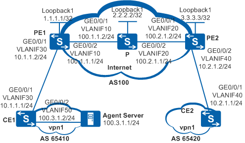
As shown in Figure 1, CE1 and CE2 need to communicate with each other, and users connected to CE1 need to connect to the Internet.
To enable users connected to CE1 to access the Internet, connect an agent server to CE1 and configure a public IP address for the agent server. Then users connected to CE1 can access the Internet through the agent server. In this example, the P represents on the Internet.
Configuration Roadmap
The configuration roadmap is as follows:
Configure basic BGP/MPLS IP VPN functions.
Configure three static routes:
On CE1, create a default route and specify PE1 as the next hop.
On PE1, configure a default route from the VPN to the Internet and specify P as the next hop. This route enables traffic to be transmitted from the agent server to the Internet.
On PE1, configure a static route from the Internet to the agent server and specify CE1 as the next hop. Configure IGP to advertise the static route to the Internet. This route enables traffic to be transmitted from the Internet to the agent server.
Procedure
- Configure VLANs on interfaces and assign IP addresses to
the VLANIF interfaces and loopback interfaces according to Figure 1.
# Configure PE1. The configuration on PE2, P, CE1, and CE2 is similar to the configuration on PE1 and is not mentioned here.
<HUAWEI> system-view
[HUAWEI] sysname PE1
[PE1] interface loopback 1
[PE1-LoopBack1] ip address 1.1.1.1 32
[PE1-LoopBack1] quit
[PE1] vlan batch 10 30
[PE1] interface gigabitethernet 0/0/1
[PE1-GigabitEthernet0/0/1] port link-type trunk
[PE1-GigabitEthernet0/0/1] port trunk allow-pass vlan 30
[PE1-GigabitEthernet0/0/1] quit
[PE1] interface gigabitethernet 0/0/2
[PE1-GigabitEthernet0/0/2] port link-type trunk
[PE1-GigabitEthernet0/0/2] port trunk allow-pass vlan 10
[PE1-GigabitEthernet0/0/2] quit
[PE1] interface vlanif 10
[PE1-Vlanif10] ip address 100.1.1.1 24
[PE1-Vlanif10] quit
- Configure an IGP protocol on the MPLS backbone network
for IP connectivity.
# Configure PE1. The configuration on PE2 and P is similar to the configuration on PE1 and is not mentioned here.
[PE1] ospf
[PE1-ospf-1] area 0
[PE1-ospf-1-area-0.0.0.0] network 1.1.1.1 0.0.0.0
[PE1-ospf-1-area-0.0.0.0] network 100.1.1.0 0.0.0.255
[PE1-ospf-1-area-0.0.0.0] quit
[PE1-ospf-1] quit

The IP addresses of loopback interfaces that are used as LSR IDs need to be advertised.
After the configuration is complete, the devices on the backbone network can obtain the loopback interface addresses from each other.
- Establish MPLS LDP LSPs and an MP-IBGP peer relationship
between the devices on the backbone network.
# Enable MPLS LDP on PE1 to establish MPLS LDP LSPs. The configuration on PE2 and P is similar to the configuration on PE1 and is not mentioned here.
[PE1] mpls lsr-id 1.1.1.1
[PE1] mpls
[PE1-mpls] quit
[PE1] mpls ldp
[PE1-mpls-ldp] quit
[PE1] interface vlanif 10
[PE1-Vlanif10] mpls
[PE1-Vlanif10] mpls ldp
[PE1-Vlanif10] quit
After the configuration is complete, run the display mpls ldp session command on the P. The command output shows that the LDP sessions between PE1 and P, and between PE2 and P are in Operational Status.
The information displayed on the P is used as an example.
[P] display mpls ldp session

 LDP Session(s) in Public Network
 Codes: LAM(Label Advertisement Mode), SsnAge Unit(DDDD:HH:MM)
 A '*' before a session means the session is being deleted.
 ------------------------------------------------------------------------------
 PeerID             Status      LAM  SsnRole  SsnAge      KASent/Rcv
 ------------------------------------------------------------------------------
 1.1.1.1:0          Operational DU   Active   0000:00:00  2/2
 3.3.3.3:0          Operational DU   Active   0000:23:08  5556/5555
 ------------------------------------------------------------------------------
 TOTAL: 2 session(s) Found.
# Configure an MP-IBGP peer on PE1. The configuration on PE2 is similar to the configuration on PE1 and is not mentioned here.
[PE1] bgp 100
[PE1-bgp] peer 3.3.3.3 as-number 100
[PE1-bgp] peer 3.3.3.3 connect-interface loopback 1
[PE1-bgp] ipv4-family vpnv4
[PE1-bgp-af-vpnv4] peer 3.3.3.3 enable
[PE1-bgp-af-vpnv4] quit
[PE1-bgp] quit
Run the display bgp vpnv4 all peer command on PE1 and PE2. The command output shows that an MP-IBGP peer relationship has been established between the PEs and is in Established state. The information displayed on PE1 is used as an example.
[PE1] display bgp vpnv4 all peer

 BGP local router ID : 1.1.1.1
 Local AS number : 100
 Total number of peers : 1                 Peers in established state : 1

  Peer            V    AS  MsgRcvd  MsgSent  OutQ  Up/Down       State PrefRcv

  3.3.3.3         4   100        6        8     0 00:03:48 Established       2
- Create VPN instances and establish EBGP peer relationships.
# Create VPN instance vpn1 on the PEs and bind the interfaces connected to CEs to vpn1. The information displayed on PE1 is used as an example. The configuration on PE2 is similar to the configuration on PE1 and is not mentioned here.
[PE1] ip vpn-instance vpn1
[PE1-vpn-instance-vpn1] ipv4-family
[PE1-vpn-instance-vpn1-af-ipv4] route-distinguisher 100:1
[PE1-vpn-instance-vpn1-af-ipv4] vpn-target 1:1 both
[PE1-vpn-instance-vpn1-af-ipv4] quit
[PE1-vpn-instance-vpn1] quit
[PE1] interface vlanif 30
[PE1-Vlanif30] ip binding vpn-instance vpn1
[PE1-Vlanif30] ip address 10.1.1.2 24
[PE1-Vlanif30] quit
Establish EBGP peer relationships between PE1 and CE1 and between PE2 and CE2 so that routes of the CEs can be advertised to the PEs. CE1 and PE1 are used as an example.
# Configure CE1. The configuration on CE2 is similar to the configuration on CE1 and is not mentioned here.
[CE1] bgp 65410
[CE1-bgp] peer 10.1.1.2 as-number 100
[CE1-bgp] import-route direct
[CE1-bgp] quit
# Configure PE1. The configuration on PE2 is similar to the configuration on PE1 and is not mentioned here.
[PE1] bgp 100
[PE1-bgp] ipv4-family vpn-instance vpn1
[PE1-bgp-vpn1] peer 10.1.1.1 as-number 65410
[PE1-bgp-vpn1] import-route direct
[PE1-bgp-vpn1] import-route static
[PE1-bgp-vpn1] quit
[PE1-bgp] quit
After the configuration is complete, run the display ip vpn-instance command on the PEs. In the command output, vpn1 is displayed in the VPN-Instance Name field.
The information displayed on PE1 is used as an example.
[PE1] display ip vpn-instance
 Total VPN-Instances configured      : 1
 Total IPv4 VPN-Instances configured : 1
 Total IPv6 VPN-Instances configured : 0

  VPN-Instance Name               RD                    Address-family
  vpn1                            100:1                 IPv4
Run the display bgp vpnv4 all peer command on the PEs. The command output shows that the IBGP and EBGP peer relationships are all in Established state.
The information displayed on PE1 is used as an example.
[PE1] display bgp vpnv4 all peer

 BGP local router ID : 1.1.1.1
 Local AS number : 100
 Total number of peers : 2                 Peers in established state : 2

  Peer            V    AS  MsgRcvd  MsgSent  OutQ  Up/Down       State PrefRcv

  3.3.3.3         4   100      127      134     0 01:39:44 Established       2

  Peer of IPv4-family for vpn instance :

 VPN-Instance vpn1, Router ID 1.1.1.1:
  10.1.1.1        4 65410      107      110     0 01:26:33 Established       3
- Configure static routes to enable VPN users to access the
Internet.
# On CE1, create a default route and specify PE1 as the next hop.
[CE1] ip route-static 0.0.0.0 0 10.1.1.2
# Configure PE1.
# Configure a default route from the agent server to the Internet and specify P as the next hop. Specify the public keyword in the command to use the public IP address of P as the next hop address.
[PE1] ip route-static vpn-instance vpn1 0.0.0.0 0 100.1.1.2 public
If the CEs and PEs are connected through an Ethernet network, you must specify the next hop when configuring the static route.
# Configure a static route from the Internet to the agent server and specify CE1 as the next hop.
[PE1] ip route-static 100.3.1.0 24 vpn-instance vpn1 10.1.1.1
# Advertise the preceding static route to the Internet using an IGP (OSPF in this example).
[PE1] ospf 1
[PE1-ospf-1] import-route static
[PE1-ospf-1] quit
# Configure the agent server. Set the IP address of the agent server to 100.3.1.1/24 and the default gateway address of the agent server to 100.3.1.2/24 (address of CE1). In addition, the agent server must run the agent software.
- Verify the configurations.
Run the display ip routing-table vpn-instance command on PE1 to check the VPN routing table of vpn1. The VPN routing table has a default route with the next hop address 100.1.1.2 and the outbound interface VLANIF10.
[PE1] display ip routing-table vpn-instance vpn1
Route Flags: R - relay, D - download to fib, T - to vpn-instance
------------------------------------------------------------------------------
Routing Tables: vpn1
         Destinations : 5        Routes : 5
  Destination/Mask  Proto  Pre  Cost         Flags  NextHop         Interface
        0.0.0.0/0   Static 60   0              RD   100.1.1.2       Vlanif10
       10.1.1.0/24  Direct 0    0               D   10.1.1.2        Vlanif30
       10.1.1.2/32  Direct 0    0               D   127.0.0.1       Vlanif30
       10.2.1.0/24  IBGP   255  0              RD   3.3.3.3         Vlanif10
      100.3.1.0/24  EBGP   255  0               D   10.1.1.1        Vlanif30
Run the display ip routing-table command on PE1 to check the IP routing table on PE1. The routing table has a route to the agent server, in which the next hop address is 10.1.1.1.
[PE1] display ip routing-table
Route Flags: R - relay, D - download to fib, T - to vpn-instance
------------------------------------------------------------------------------
Routing Tables: Public
         Destinations : 9       Routes : 9
  Destination/Mask  Proto  Pre  Cost         Flags  NextHop         Interface
        1.1.1.1/32  Direct 0    0               D   127.0.0.1       LoopBack1
        2.2.2.2/32  OSPF   10   1               D   100.1.1.2       Vlanif10
        3.3.3.3/32  OSPF   10   2               D   100.1.1.2       Vlanif10
      100.1.1.0/24  Direct 0    0               D   100.1.1.1       Vlanif10
      100.1.1.1/32  Direct 0    0               D   127.0.0.1       Vlanif10
      100.2.1.0/24  OSPF   10   2               D   100.1.1.2       Vlanif10
      100.3.1.0/24  Static 60   0              RD   10.1.1.1        Vlanif30
       127.0.0.0/8  Direct 0    0               D   127.0.0.1       InLoopBack0
      127.0.0.1/32  Direct 0    0               D   127.0.0.1       InLoopBack0
P can ping the agent server.
[P] ping 100.3.1.1
  PING 100.3.1.1: 56  data bytes, press CTRL_C to break
    Reply from 100.3.1.1: bytes=56 Sequence=1 ttl=254 time=62 ms
    Reply from 100.3.1.1: bytes=56 Sequence=2 ttl=254 time=62 ms
    Reply from 100.3.1.1: bytes=56 Sequence=3 ttl=254 time=62 ms
    Reply from 100.3.1.1: bytes=56 Sequence=4 ttl=254 time=62 ms
    Reply from 100.3.1.1: bytes=56 Sequence=5 ttl=254 time=62 ms

  --- 100.3.1.1 ping statistics ---
    5 packet(s) transmitted
    5 packet(s) received
    0.00% packet loss
    round-trip min/avg/max = 62/62/62 ms
The agent server can access the P on the Internet.
Configuration Files
CE1 configuration file
#
sysname CE1
#
vlan batch 30 50
#
interface Vlanif30
 ip address 10.1.1.1 255.255.255.0
#
interface Vlanif50
 ip address 100.3.1.2 255.255.255.0
#
interface GigabitEthernet0/0/1
 port link-type trunk
 port trunk allow-pass vlan 30
#
interface GigabitEthernet0/0/2
 port link-type trunk
 port trunk allow-pass vlan 50
#
bgp 65410
 peer 10.1.1.2 as-number 100
 #
 ipv4-family unicast
  undo synchronization
  import-route direct
  peer 10.1.1.2 enable
#
ip route-static 0.0.0.0 0.0.0.0 10.1.1.2
#
return
PE1 configuration file
#
sysname PE1
#
vlan batch 10 30
#
ip vpn-instance vpn1
 ipv4-family
  route-distinguisher 100:1
  vpn-target 1:1 export-extcommunity
  vpn-target 1:1 import-extcommunity
#
mpls lsr-id 1.1.1.1
mpls
#
mpls ldp
#
interface Vlanif10
 ip address 100.1.1.1 255.255.255.0
 mpls
 mpls ldp
#
interface Vlanif30
 ip binding vpn-instance vpn1
 ip address 10.1.1.2 255.255.255.0
#
interface GigabitEthernet0/0/1
 port link-type trunk
 port trunk allow-pass vlan 30
#
interface GigabitEthernet0/0/2
 port link-type trunk
 port trunk allow-pass vlan 10
#
interface LoopBack1
 ip address 1.1.1.1 255.255.255.255
#
bgp 100
 peer 3.3.3.3 as-number 100
 peer 3.3.3.3 connect-interface LoopBack1
 #
 ipv4-family unicast
  undo synchronization
  peer 3.3.3.3 enable
 #
 ipv4-family vpnv4
  policy vpn-target
  peer 3.3.3.3 enable
 #
 ipv4-family vpn-instance vpn1
  import-route direct
  import-route static
  peer 10.1.1.1 as-number 65410
#
ospf 1
 import-route static
 area 0.0.0.0
  network 1.1.1.1 0.0.0.0
  network 100.1.1.0 0.0.0.255
#
ip route-static 100.3.1.0 255.255.255.0 vpn-instance vpn1 10.1.1.1
ip route-static vpn-instance vpn1 0.0.0.0 0.0.0.0 100.1.1.2 public
#
return
P configuration file
#
sysname P
#
vlan batch 10 20
#
mpls lsr-id 2.2.2.2
mpls
#
mpls ldp
#
interface Vlanif10
 ip address 100.1.1.2 255.255.255.0
 mpls
 mpls ldp
#
interface Vlanif20
 ip address 100.2.1.1 255.255.255.0
 mpls
 mpls ldp
#
interface GigabitEthernet0/0/1
 port link-type trunk
 port trunk allow-pass vlan 10
#
interface GigabitEthernet0/0/2
 port link-type trunk
 port trunk allow-pass vlan 20
#
interface LoopBack1
 ip address 2.2.2.2 255.255.255.255
#
ospf 1
 area 0.0.0.0
  network 2.2.2.2 0.0.0.0
  network 100.1.1.0 0.0.0.255
  network 100.2.1.0 0.0.0.255
#
return
PE2 configuration file
#
sysname PE2
#
vlan batch 20 40
#
ip vpn-instance vpn1
 ipv4-family
  route-distinguisher 100:2
  vpn-target 1:1 export-extcommunity
  vpn-target 1:1 import-extcommunity
#
mpls lsr-id 3.3.3.3
mpls
#
mpls ldp
#
interface Vlanif20
 ip address 100.2.1.2 255.255.255.0
 mpls
 mpls ldp
#
interface Vlanif40
 ip binding vpn-instance vpn1
 ip address 10.2.1.2 255.255.255.0
#
interface GigabitEthernet0/0/1
 port link-type trunk
 port trunk allow-pass vlan 20
#
interface GigabitEthernet0/0/2
 port link-type trunk
 port trunk allow-pass vlan 40
#
interface LoopBack1
 ip address 3.3.3.3 255.255.255.255
#
bgp 100
 peer 1.1.1.1 as-number 100
 peer 1.1.1.1 connect-interface LoopBack1
 #
 ipv4-family unicast
  undo synchronization
  peer 1.1.1.1 enable
 #
 ipv4-family vpnv4
  policy vpn-target
  peer 1.1.1.1 enable
 #
 ipv4-family vpn-instance vpn1
  import-route direct
  peer 10.2.1.1 as-number 65420
#
ospf 1
 area 0.0.0.0
  network 3.3.3.3 0.0.0.0
  network 100.2.1.0 0.0.0.255
#
return
CE2 configuration file
#
sysname CE2
#
vlan batch 40
#
interface Vlanif40
 ip address 10.2.1.1 255.255.255.0
#
interface GigabitEthernet0/0/1
 port link-type trunk
 port trunk allow-pass vlan 40
#
bgp 65420
 peer 10.2.1.2 as-number 100
 #
 ipv4-family unicast
  undo synchronization
  import-route direct
  peer 10.2.1.2 enable
#
return