Example for Configuring Basic BGP/MPLS IPv6 VPN
Networking Requirements
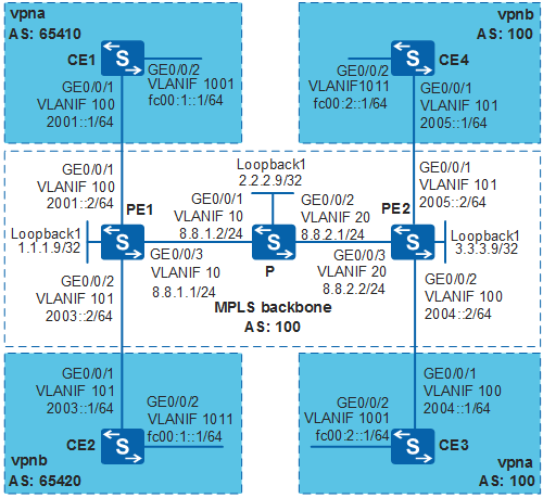
- CE1 connects to the headquarters R&D area of the company, and CE3 connects to the branch R&D area. CE1 and CE3 belong to vpna.
- CE2 connects to the headquarters non-R&D area, and CE4 connects to the branch non-R&D area. CE2 and CE4 belong to vpnb.
BGP/MPLS IPv6 VPN needs to be deployed for the company to ensure secure communication between the headquarters and branch and to isolate the R&D areas from non-R&D areas.
Configuration Roadmap
The configuration roadmap is as follows:
Configure IS-IS on the IPv4 public network to implement connectivity on the backbone network.
Configure MPLS and MPLS LDP on each PE and P. That is, the VPN uses the LDP LSP on the IPv4 public network to transmit VPN data.
Configure MP-IBGP on PE1 and PE2. That is, the PEs exchange IPv6 VPN routes using BGP.
Configure VPN instances on PE1 and PE2 and configure proper VPN targets. This configuration allows users in the same VPN to communicate with each other and isolates users in different VPNs. Bind the PE interfaces connected to CEs to the corresponding VPN instances to provide access for VPN users.
Configure the IPv6 routing protocol on each PE and CE so that the PEs and CEs can learn the IPv6 routes of each other.
Procedure
- Configure the IPv6 packet forwarding capability
on each CE and PE.
# Enable the IPv6 forwarding capability on CE1.
<HUAWEI> system-view
[HUAWEI] sysname CE1
[CE1] ipv6
The configuration on CE2, CE3, CE4, PE1, and PE2 is similar to the configuration on CE1 and is not mentioned here.
- Create VLANs, configure the VLAN ID allowed by each interface,
and assign IP addresses to the VLANIF interfaces except for the interfaces
that connect PEs to CEs. For the data plan, see Figure 1.
- Configure an IGP on the backbone network to ensure the
connectivity of the backbone network. The IS-IS protocol is used in
this example.
# Configure IS-IS on PE1.
[PE1] isis 1
[PE1-isis-1] network-entity 10.1111.1111.1111.00
[PE1-isis-1] quit
[PE1] interface vlanif 10
[PE1-Vlanif10] isis enable 1
[PE1-Vlanif10] quit
[PE1] interface loopback 1
[PE1-LoopBack1] isis enable 1
[PE1-LoopBack1] quit
The configuration on P and PE2 is similar to the configuration on PE1 and is not mentioned here.
After the configuration is complete, PE1, P, and PE2 can learn the routes of each other, including the routes on the loopback1 interface. You can view the routes using the display ip routing-table command.
- Establish a tunnel between PE1 and PE2.
An MPLS LDP LSP is used in this example.
# Enable MPLS and MPLS LDP on PE1.
[PE1] mpls lsr-id 1.1.1.9
[PE1] mpls
[PE1-mpls] quit
[PE1] mpls ldp
[PE1-mpls-ldp] quit
[PE1] interface vlanif 10
[PE1-Vlanif10] mpls
[PE1-Vlanif10] mpls ldp
[PE1-Vlanif10] quit
# Enable MPLS and MPLS LDP on P.
[P] mpls lsr-id 2.2.2.9
[P] mpls
[P-mpls] quit
[P] mpls ldp
[P-mpls-ldp] quit
[P] interface vlanif 10
[P-Vlanif10] mpls
[P-Vlanif10] mpls ldp
[P-Vlanif10] quit
[P] interface vlanif 20
[P-Vlanif20] mpls
[P-Vlanif20] mpls ldp
[P-Vlanif20] quit
# Enable MPLS and MPLS LDP on PE2.
[PE2] mpls lsr-id 3.3.3.9
[PE2] mpls
[PE2-mpls] quit
[PE2] mpls ldp
[PE2-mpls-ldp] quit
[PE2] interface vlanif 20
[PE2-Vlanif20] mpls
[PE2-Vlanif20] mpls ldp
[PE2-Vlanif20] quit
After the configuration is complete, an LDP LSP is established between PE1 and PE2. Run the display mpls ldp lsp command. Information about the established LDP LSP is displayed.
- Configure VPN instances on PE1 and PE2.
# Configure VPN instance vpna on PE1.
[PE1] ip vpn-instance vpna
[PE1-vpn-instance-vpna] ipv6-family
[PE1-vpn-instance-vpna-af-ipv6] route-distinguisher 100:1
[PE1-vpn-instance-vpna-af-ipv6] vpn-target 22:22 export-extcommunity
[PE1-vpn-instance-vpna-af-ipv6] vpn-target 33:33 import-extcommunity
[PE1-vpn-instance-vpna-af-ipv6] quit
[PE1-vpn-instance-vpna] quit
# Bind the interface connected PE1 to CE1 to VPN instances vpna.
[PE1] interface vlanif 100
[PE1-Vlanif100] ipv6 enable
[PE1-Vlanif100] ip binding vpn-instance vpna
[PE1-Vlanif100] ipv6 address 2001::2 64
[PE1-Vlanif100] quit
# Configure VPN instances vpnb on PE1.
[PE1] ip vpn-instance vpnb
[PE1-vpn-instance-vpnb] ipv6-family
[PE1-vpn-instance-vpnb-af-ipv6] route-distinguisher 200:1
[PE1-vpn-instance-vpnb-af-ipv6] vpn-target 44:44 export-extcommunity
[PE1-vpn-instance-vpnb-af-ipv6] vpn-target 55:55 import-extcommunity
[PE1-vpn-instance-vpnb-af-ipv6] quit
[PE1-vpn-instance-vpnb] quit
# Bind the interface connected PE1 to CE2 to VPN instances vpnb.
[PE1] interface vlanif 101
[PE1-Vlanif101] ipv6 enable
[PE1-Vlanif101] ip binding vpn-instance vpnb
[PE1-Vlanif101] ipv6 address 2003::2 64
[PE1-Vlanif101] quit
# Configure VPN instances vpna on PE2.
[PE2] ip vpn-instance vpna
[PE2-vpn-instance-vpna] ipv6-family
[PE2-vpn-instance-vpna-af-ipv6] route-distinguisher 300:1
[PE2-vpn-instance-vpna-af-ipv6] vpn-target 33:33 export-extcommunity
[PE2-vpn-instance-vpna-af-ipv6] vpn-target 22:22 import-extcommunity
[PE2-vpn-instance-vpna-af-ipv6] quit
[PE2-vpn-instance-vpna] quit
# Bind the interface connected PE2 to CE3 to VPN instances vpna.
[PE2] interface vlanif 100
[PE2-Vlanif100] ipv6 enable
[PE2-Vlanif100] ip binding vpn-instance vpna
[PE2-Vlanif100] ipv6 address 2004::2 64
[PE2-Vlanif100] quit
# Configure VPN instances vpnb on PE2.
[PE2] ip vpn-instance vpnb
[PE2-vpn-instance-vpnb] ipv6-family
[PE2-vpn-instance-vpnb-af-ipv6] route-distinguisher 400:1
[PE2-vpn-instance-vpnb-af-ipv6] vpn-target 55:55 export-extcommunity
[PE2-vpn-instance-vpnb-af-ipv6] vpn-target 44:44 import-extcommunity
[PE2-vpn-instance-vpnb-af-ipv6] quit
[PE2-vpn-instance-vpnb] quit
# Bind the interface connected PE2 to CE4 to VPN instances vpnb.
[PE2] interface vlanif 101
[PE2-Vlanif101] ipv6 enable
[PE2-Vlanif101] ip binding vpn-instance vpnb
[PE2-Vlanif101] ipv6 address 2005::2 64
[PE2-Vlanif101] quit
After the configuration is complete, run the display ip vpn-instance verbose command on each PE to view information about the VPN instances. Each PE can ping its connected CE. The information displayed on PE1 is used as an example.
[PE1] display ip vpn-instance verbose
 Total VPN-Instances configured      : 2
 Total IPv4 VPN-Instances configured : 0
 Total IPv6 VPN-Instances configured : 2

 VPN-Instance Name and ID : vpna, 3
  Interfaces : Vlanif100
 Address family ipv6
  Create date : 2012-09-05 15:51:15+00:00
  Up time : 0 days, 00 hours, 00 minutes and 22 seconds
  Route Distinguisher : 100:1
  Export VPN Targets :  22:22
  Import VPN Targets :  33:33
  Label Policy : label per instance
  Per-Instance Label : 4096
  Log Interval : 5

 VPN-Instance Name and ID : vpnb, 4
  Interfaces : Vlanif101
 Address family ipv6
  Create date : 2012-09-05 15:12:49+00:00
  Up time : 0 days, 00 hours, 38 minutes and 48 seconds
  Route Distinguisher : 200:1
  Export VPN Targets :  44:44
  Import VPN Targets :  55:55
  Label Policy : label per instance
  Per-Instance Label : 4097
  Log Interval : 5
[PE1] ping ipv6 vpn-instance vpna 2001::1 PING 2001::1 : 56 data bytes, press CTRL_C to break Reply from 2001::1 bytes=56 Sequence=1 hop limit=64 time = 47 ms Reply from 2001::1 bytes=56 Sequence=2 hop limit=64 time = 31 ms Reply from 2001::1 bytes=56 Sequence=3 hop limit=64 time = 62 ms Reply from 2001::1 bytes=56 Sequence=4 hop limit=64 time = 62 ms Reply from 2001::1 bytes=56 Sequence=5 hop limit=64 time = 31 ms --- 2001::1 ping statistics --- 5 packet(s) transmitted 5 packet(s) received 0.00% packet loss round-trip min/avg/max = 31/46/62 ms - Establish the VPNv6 peer relationship between PE1 and PE2.
# Configure BGP on PE1.
[PE1] bgp 100
[PE1-bgp] peer 3.3.3.9 as-number 100
[PE1-bgp] peer 3.3.3.9 connect-interface loopback 1
[PE1-bgp] ipv6-family vpnv6
[PE1-bgp-af-vpnv6] peer 3.3.3.9 enable
[PE1-bgp-af-vpnv6] quit
# Configure BGP on PE2.
[PE2] bgp 100
[PE2-bgp] peer 1.1.1.9 as-number 100
[PE2-bgp] peer 1.1.1.9 connect-interface loopback 1
[PE2-bgp] ipv6-family vpnv6
[PE2-bgp-af-vpnv6] peer 1.1.1.9 enable
[PE2-bgp-af-vpnv6] quit
After the configuration is complete, run the display bgp vpnv6 all peer command on a PE to view the status of VPNv6 peer relationship. The information displayed on PE1 is used as an example.
[PE1] display bgp vpnv6 all peer
BGP local router ID : 1.1.1.9
 Local AS number : 100
 Total number of peers : 1                 Peers in established state : 1

  Peer            V    AS  MsgRcvd  MsgSent  OutQ  Up/Down       State PrefRcv

  3.3.3.9         4   100        3        3     0 00:02:19 Established       0
You can see that a VPNv6 peer relationship is established between PE1 and PE2.
- Configure BGP4+ on PE1 and CE1.
# Configure EBGP on PE1.
[PE1] bgp 100
[PE1-bgp] ipv6-family vpn-instance vpna
[PE1-bgp6-vpna] peer 2001::1 as-number 65410
[PE1-bgp6-vpna] import-route direct
[PE1-bgp6-vpna] quit
[PE1-bgp] quit
# Configure EBGP on CE1.
[CE1] bgp 65410
[CE1-bgp] router-id 10.10.10.10
[CE1-bgp] peer 2001::2 as-number 100
[CE1-bgp] ipv6-family unicast
[CE1-bgp-af-ipv6] peer 2001::2 enable
[CE1-bgp-af-ipv6] import-route direct
[CE1-bgp-af-ipv6] quit
[CE1-bgp] quit
After the configuration is complete, run the display bgp vpnv6 all peer command on PE1 to view the status of the peer relationship.
[PE1] display bgp vpnv6 all peer

 BGP local router ID : 1.1.1.9
 Local AS number : 100
 Total number of peers : 1                Peers in established state : 0

  Peer            V          AS  MsgRcvd  MsgSent  OutQ  Up/Down       State PrefRcv

  2001::1         4       65410        0        0     0 00:24:31     Established   0
You can also run the display bgp ipv6 peer command on CE1 to view the status of the peer relationship.
[CE1] display bgp ipv6 peer

 BGP local router ID : 10.10.10.10
 Local AS number : 65410
 Total number of peers : 1                Peers in established state : 0

  Peer            V          AS  MsgRcvd  MsgSent  OutQ  Up/Down       State PrefRcv

  2001::2         4         100        0        0     0 00:35:04     Established   0
You can see that the EBGP connection is established between PE1 and CE1.
- Configure a static route between PE1 and CE2.
# Configure an IPv6 static route for the VPN instances vpnb on PE1.
[PE1] ipv6 route-static vpn-instance vpnb fc00:1:: 64 2003::1
# Import the static route and direct route to BGP on PE1.
[PE1] bgp 100
[PE1-bgp] ipv6-family vpn-instance vpnb
[PE1-bgp6-vpnb] import-route static
[PE1-bgp6-vpnb] import-route direct
[PE1-bgp6-vpnb] quit
[PE1-bgp] quit
# Configure the IPv6 default route on CE2.
[CE2] ipv6 route-static :: 0 2003::2
- Configure IS-ISv6 on PE2 and CE3.
# Configure IS-ISv6 on PE2.
[PE2] isis 10 vpn-instance vpna
[PE2-isis-10] network-entity 30.4444.4444.4444.4444.00
[PE2-isis-10] ipv6 enable
[PE2-isis-10] ipv6 import-route bgp
[PE2-isis-10] quit
[PE2] interface vlanif 100
[PE2-Vlanif100] isis ipv6 enable 10
[PE2-Vlanif100] quit
# Import IS-ISv6 routes to BGP on PE2.
[PE2] bgp 100
[PE2-bgp] ipv6-family vpn-instance vpna
[PE2-bgp6-vpna] import-route isis 10
[PE2-bgp6-vpna] quit
[PE2-bgp] quit
# Configure IS-ISv6 on CE3.
[CE3] isis 10
[CE3-isis-10] network-entity 30.2222.2222.2222.00
[CE3-isis-10] ipv6 enable
[CE3-isis-10] quit
[CE3] interface vlanif 100
[CE3-Vlanif100] isis ipv6 enable 10
[CE3-Vlanif100] quit
[CE3] interface vlanif 1001
[CE3-Vlanif1001] isis ipv6 enable 10
[CE3-Vlanif1001] quit
- Configure RIPng on PE2 and CE4.
# Configure RIPng on PE2.
[PE2] ripng 100 vpn-instance vpnb
[PE2-ripng-100] import-route bgp
[PE2-ripng-100] quit
[PE2] interface vlanif 101
[PE2-Vlanif101] ripng 100 enable
[PE2-Vlanif101] quit
# Import RIPng routes to BGP on PE2.
[PE2] bgp 100
[PE2-bgp] ipv6-family vpn-instance vpnb
[PE2-bgp6-vpnb] import-route ripng 100
[PE2-bgp6-vpnb] quit
[PE2-bgp] quit
# Configure RIPng on CE4.
[CE4] ripng 100
[CE4-ripng-100] quit
[CE4] interface vlanif 101
[CE4-Vlanif101] ripng 100 enable
[CE4-Vlanif101] quit
[CE4] interface vlanif 1011
[CE4-Vlanif1011] ripng 100 enable
[CE4-Vlanif1011] quit
- Verify the configuration.
After the preceding configurations are complete, the CEs can learn the routes of each other. Run the display ipv6 routing-table vpn-instance command on each PE to view the routes of the VPN instances. You can also run the ping or tracert command to verify the configuration. In addition, you can run the display ipv6 routing-table, ping, or tracert command on each CE to verify the configuration. The information displayed on PE1 and CE1 is used as an example.
[PE1] ping ipv6 vpn-instance vpna fc00:2::1
  PING FC00:2::1 : 56  data bytes, press CTRL_C to break
    Reply from FC00:2::1
    bytes=56 Sequence=1 hop limit=63  time = 94 ms
    Reply from FC00:2::1
    bytes=56 Sequence=2 hop limit=63  time = 94 ms
    Reply from FC00:2::1
    bytes=56 Sequence=3 hop limit=63  time = 94 ms
    Reply from FC00:2::1
    bytes=56 Sequence=4 hop limit=63  time = 94 ms
    Reply from FC00:2::1
    bytes=56 Sequence=5 hop limit=63  time = 94 ms

  --- FC00:2::1 ping statistics ---
    5 packet(s) transmitted
    5 packet(s) received
    0.00% packet loss
    round-trip min/avg/max = 94/94/94 ms

[CE1] tracert ipv6 fc00:2::1
 traceroute to FC00:2::1  30 hops max,60 bytes packet
 1 2001::2 62 ms  31 ms  32 ms
 2 2004::2 101 ms  94 ms  98 ms
 3 FC00:2::1 156 ms  157 ms  171 ms
The address fc00:2::1/64 also exists on CE4. Therefore, when you run the display ipv6 statistics command on CE3 and CE4 to check the change of the number of sent and received ICMPv6 packets, you can see that the packets are sent to the correct interface. The sites that are not allowed to communicate with each other are separated.
Configuration Files
PE1 configuration file
#
sysname PE1
#
ipv6
#
vlan batch 10 100 101
#
ip vpn-instance vpna
 ipv6-family
  route-distinguisher 100:1
  vpn-target 22:22 export-extcommunity
  vpn-target 33:33 import-extcommunity
#
ip vpn-instance vpnb
 ipv6-family
  route-distinguisher 200:1
  vpn-target 44:44 export-extcommunity
  vpn-target 55:55 import-extcommunity
#
mpls lsr-id 1.1.1.9
mpls
#
mpls ldp
#
isis 1
 network-entity 10.1111.1111.1111.00
#
interface Vlanif100
 ipv6 enable
 ip binding vpn-instance vpna
 ipv6 address 2001::2/64
#
interface Vlanif101
 ipv6 enable
 ip binding vpn-instance vpnb
 ipv6 address 2003::2/64
#
interface Vlanif10
 ip address 8.8.1.1 255.255.255.0
 isis enable 1
 mpls
 mpls ldp
#
interface GigabitEthernet0/0/1
 port link-type trunk
 port trunk allow-pass vlan 100
#
interface GigabitEthernet0/0/2
 port link-type trunk
 port trunk allow-pass vlan 101
#
interface GigabitEthernet0/0/3
 port link-type trunk
 port trunk allow-pass vlan 10
#
interface LoopBack1
 ip address 1.1.1.9 255.255.255.255
 isis enable 1
#
bgp 100
 peer 3.3.3.9 as-number 100
 peer 3.3.3.9 connect-interface LoopBack1
 #
 ipv4-family unicast
  undo synchronization
  peer 3.3.3.9 enable
 #
 ipv6-family vpnv6
  policy vpn-target
  peer 3.3.3.9 enable
 #
 ipv6-family vpn-instance vpna
  import-route direct
  peer 2001::1 as-number 65410
 #
 ipv6-family vpn-instance vpnb
  import-route direct
  import-route static
#
ipv6 route-static vpn-instance vpnb fc00:1:: 64 2003::1
#
return
P configuration file
#
sysname P
#
vlan batch 10 20
#
mpls lsr-id 2.2.2.9
mpls
#
mpls ldp
#
isis 1
 network-entity 10.2222.2222.2222.00
#
interface Vlanif10
 ip address 8.8.1.2 255.255.255.0
 isis enable 1
 mpls
 mpls ldp
#
interface Vlanif20
 ip address 8.8.2.1 255.255.255.0
 isis enable 1
 mpls
 mpls ldp
#
interface GigabitEthernet0/0/1
 port link-type trunk
 port trunk allow-pass vlan 10
#
interface GigabitEthernet0/0/2
 port link-type trunk
 port trunk allow-pass vlan 20
#
interface LoopBack1
 ip address 2.2.2.9 255.255.255.255
 isis enable 1
#
return
PE2 configuration file
#
sysname PE2
#
ipv6
#
vlan batch 20 100 101
#
ip vpn-instance vpna
 ipv6-family
  route-distinguisher 300:1
  vpn-target 33:33 export-extcommunity
  vpn-target 22:22 import-extcommunity
#
ip vpn-instance vpnb
 ipv6-family
  route-distinguisher 400:1
  vpn-target 55:55 export-extcommunity
  vpn-target 44:44 import-extcommunity
#
mpls lsr-id 3.3.3.9
mpls
#
mpls ldp
#
isis 1
 network-entity 10.3333.3333.3333.00
#
isis 10 vpn-instance vpna
 network-entity 30.4444.4444.4444.4444.00
 #
 ipv6 enable topology standard
 ipv6 import-route bgp
 #
#
interface Vlanif20
 ip address 8.8.2.2 255.255.255.0
 isis enable 1
 mpls
 mpls ldp
#
interface Vlanif100
 ip binding vpn-instance vpna
 ipv6 enable
 ipv6 address 2004::2/64
 isis ipv6 enable 10
#
interface Vlanif101
 ip binding vpn-instance vpnb
 ipv6 enable
 ipv6 address 2005::2/64
 ripng 100 enable
#
interface GigabitEthernet0/0/1
 port link-type trunk
 port trunk allow-pass vlan 101
#
interface GigabitEthernet0/0/2
 port link-type trunk
 port trunk allow-pass vlan 100
#
interface GigabitEthernet0/0/3
 port link-type trunk
 port trunk allow-pass vlan 20
#
interface LoopBack1
 ip address 3.3.3.9 255.255.255.255
 isis enable 1
#
bgp 100
 peer 1.1.1.9 as-number 100
 peer 1.1.1.9 connect-interface LoopBack1
 #
 ipv4-family unicast
  undo synchronization
  peer 1.1.1.9 enable
 #
 ipv6-family vpnv6
  policy vpn-target
  peer 1.1.1.9 enable
 #
 ipv6-family vpn-instance vpna
  import-route isis 10
 #
 ipv6-family vpn-instance vpnb
  import-route ripng 100
#
ripng 100 vpn-instance vpnb
 import-route bgp
#
return
CE1 configuration file (connected to the headquarters R&D area)
#
sysname CE1
#
ipv6
#
vlan batch 100 1001
#
interface Vlanif100
 ipv6 enable
 ipv6 address 2001::1/64
#
interface Vlanif1001
 ipv6 enable
 ipv6 address FC00:1::1/64
#
interface GigabitEthernet0/0/1
 port link-type trunk
 port trunk allow-pass vlan 100
#
interface GigabitEthernet0/0/2
 port link-type trunk
 port trunk allow-pass vlan 1001
#
bgp 65410
 router-id 10.10.10.10
 peer 2001::2 as-number 100
 #
 ipv6-family unicast
  undo synchronization
  import-route direct
  peer 2001::2 enable
#
return
CE2 configuration file (connected to the headquarters non-R&D area)
#
sysname CE2
#
ipv6
#
vlan batch 101 1011
#
interface Vlanif101
 ipv6 enable
 ipv6 address 2003::1/64
#
interface Vlanif1011
 ipv6 enable
 ipv6 address FC00:1::1/64
#
interface GigabitEthernet0/0/1
 port link-type trunk
 port trunk allow-pass vlan 101
#
interface GigabitEthernet0/0/2
 port link-type trunk
 port trunk allow-pass vlan 1011
#
ipv6 route-static :: 0 2003::2
#
return
CE3 configuration file (connected to the branch R&D area)
#
sysname CE3
#
ipv6
#
vlan batch 100 1001
#
isis 10
 network-entity 30.2222.2222.2222.00
 #
 ipv6 enable topology standard
 #
#
interface Vlanif100
 ipv6 enable
 ipv6 address 2004::1/64
 isis ipv6 enable 10
#
interface Vlanif1001
 ipv6 enable
 ipv6 address FC00:2::1/64
 isis ipv6 enable 10
#
interface GigabitEthernet0/0/1
 port link-type trunk
 port trunk allow-pass vlan 100
#
interface GigabitEthernet0/0/2
 port link-type trunk
 port trunk allow-pass vlan 1001
#
return
CE4 configuration file (connected to the branch non-R&D area)
#
sysname CE4
#
ipv6
#
vlan batch 101 1011
#
interface Vlanif101
 ipv6 enable
 ipv6 address 2005::1/64
 ripng 100 enable
#
interface Vlanif1011
 ipv6 enable
 ipv6 address FC00:2::1/64
 ripng 100 enable
#
interface GigabitEthernet0/0/1
 port link-type trunk
 port trunk allow-pass vlan 101
#
interface GigabitEthernet0/0/2
 port link-type trunk1
 port trunk allow-pass vlan 1011
#
ripng 100
#
return