Example for Configuring Inter-AS IPv6 VPN Option A
Networking Requirements
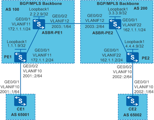
The headquarters and branches of a company connect to networks of different carriers. To enable the headquarters and branches to communicate, Inter-AS BGP/MPLS IPv6 VPN needs to be implemented. As shown in Figure 1, CE1 is located in the headquarters and connects to PE1 in AS 100. CE2 is located at the branch and connects to PE2 in AS 200. Both CE1 and CE2 belong to VPN1.
Configuration Roadmap
Inter-AS Option A can be deployed to meet the company's requirement. The configuration roadmap is as follows:
- On the MPLS backbone networks in AS 100 and AS 200, configure an IGP protocol to enable the PEs and ASBR-PEs to communicate with each other.
- Configure basic MPLS capabilities and MPLS LDP on the MPLS backbone network to establish LDP LSPs in each AS.
- Establish an MP-IBGP peer relationship between the PE and ASBR-PE in each AS to exchange VPN routing information.
- Configure a VPN instance on the PE in each AS and bind the interface connected to the CE to the VPN instance.
- Establish an EBGP peer relationship between the PE and CE in each AS to exchange VPN routing information.
- Create an IPv6 VPN instance on each ASBR-PE and bind the instance to the interface connected to the other ASBR-PE (regarding the ASBR-PE as its CE). Establish an EBGP peer relationship between the ASBR-PEs to exchange VPN routing information.
Procedure
- Create VLANs, configure the allowed VLANs on interfaces, and assign IP addresses to the VLANIF interfaces and loopback interfaces according to Figure 1.
# Configure PE1.
<HUAWEI> system-view
[HUAWEI] sysname PE1
[PE1] interface loopback 1
[PE1-LoopBack1] ip address 1.1.1.9 32
[PE1-LoopBack1] quit
[PE1] ipv6
[PE1] vlan batch 10 11
[PE1] interface gigabitethernet 0/0/1
[PE1-GigabitEthernet0/0/1] port link-type trunk
[PE1-GigabitEthernet0/0/1] port trunk allow-pass vlan 11
[PE1-GigabitEthernet0/0/1] quit
[PE1] interface gigabitethernet 0/0/2
[PE1-GigabitEthernet0/0/2] port link-type trunk
[PE1-GigabitEthernet0/0/2] port trunk allow-pass vlan 10
[PE1-GigabitEthernet0/0/2] quit
[PE1] interface vlanif 11
[PE1-Vlanif11] ip address 172.1.1.2 24
[PE1-Vlanif11] quit
[PE1] interface vlanif 10
[PE1-Vlanif10] ipv6 enable
[PE1-Vlanif10] ipv6 address 2001::2 64
[PE1-Vlanif10] quit
The configuration on PE2, CE1, CE2, ASBR-PE1, and ASBR-PE2 is similar to the configuration on PE1 and is not mentioned here.
- On the MPLS backbone networks in AS 100 and AS 200, configure an IGP protocol to enable the PEs and ASBR-PEs to communicate with each other.
# Configure PE1.
[PE1] ospf
[PE1-ospf-1] area 0
[PE1-ospf-1-area-0.0.0.0] network 1.1.1.9 0.0.0.0
[PE1-ospf-1-area-0.0.0.0] network 172.1.1.0 0.0.0.255
[PE1-ospf-1-area-0.0.0.0] quit
[PE1-ospf-1] quit
The configuration on PE2 and ASBR-PEs is similar to the configuration on PE1 and is not mentioned here.
After the configuration is complete, the ASBR-PE and PE in the same AS can establish an OSPF neighbor relationship. Run the display ospf peer command to verify that the status of the neighbor relationship is Full.
The ASBR-PE and PE in the same AS have obtained the address of Loopback1 interface of each other and can ping Loopback1 interface address of each other.
- Configure basic MPLS capabilities and MPLS LDP on the MPLS backbone networks of AS 100 and AS 200 respectively and establish MPLS LDP LSPs.
# Configure basic MPLS capabilities on PE1 and enable LDP on the interface connected to ASBR-PE1.
[PE1] mpls lsr-id 1.1.1.9
[PE1] mpls
[PE1-mpls] quit
[PE1] mpls ldp
[PE1-mpls-ldp] quit
[PE1] interface vlanif 11
[PE1-Vlanif11] mpls
[PE1-Vlanif11] mpls ldp
[PE1-Vlanif11] quit
# Configure basic MPLS capabilities on ASBR-PE1 and enable LDP on the interface connected to PE1.
[ASBR-PE1] mpls lsr-id 2.2.2.9
[ASBR-PE1] mpls
[ASBR-PE1-mpls] quit
[ASBR-PE1] mpls ldp
[ASBR-PE1-mpls-ldp] quit
[ASBR-PE1] interface vlanif 11
[ASBR-PE1-Vlanif11] mpls
[ASBR-PE1-Vlanif11] mpls ldp
[ASBR-PE1-Vlanif11] quit
# Configure basic MPLS capabilities on ASBR-PE2 and enable LDP on the interface connected to PE2.
[ASBR-PE2] mpls lsr-id 3.3.3.9
[ASBR-PE2] mpls
[ASBR-PE2-mpls] quit
[ASBR-PE2] mpls ldp
[ASBR-PE2-mpls-ldp] quit
[ASBR-PE2] interface vlanif 22
[ASBR-PE2-Vlanif22] mpls
[ASBR-PE2-Vlanif22] mpls ldp
[ASBR-PE2-Vlanif22] quit
# Configure basic MPLS capabilities on PE2 and enable LDP on the interface connected to ASBR-PE2.
[PE2] mpls lsr-id 4.4.4.9
[PE2] mpls
[PE2-mpls] lsp-trigger all
[PE2-mpls] quit
[PE2] mpls ldp
[PE2-mpls-ldp] quit
[PE2] interface vlanif 22
[PE2-Vlanif22] mpls
[PE2-Vlanif22] mpls ldp
[PE2-Vlanif22] quit
After the configuration is complete, the PE and ASBR-PE in the same AS can establish an LDP peer relationship. Run the display mpls ldp session command on the PE and ASBR-PE, and you can see that the status is Operational.
- Configure the basic BGP/MPLS IPv6 VPNs in AS 100 and AS 200.

The VPN targets of the IPv6 VPN instances on the ASBR-PE and PE in an AS must match. In different ASs, the VPN targets of the PEs do not need to match.
# Configure CE1. The configuration on CE2 is similar to the configuration on CE1 and is not mentioned here.
[CE1] interface vlanif 10
[CE1-Vlanif10] ipv6 enable
[CE1-Vlanif10] ipv6 address 2001::1 64
[CE1-Vlanif10] quit
[CE1] bgp 65001
[CE1-bgp] router-id 10.10.10.10
[CE1-bgp] peer 2001::2 as-number 100
[CE1-bgp] ipv6-family unicast
[CE1-bgp-af-ipv6] peer 2001::2 enable
[CE1-bgp-af-ipv6] import-route direct
[CE1-bgp-af-ipv6] quit
[CE1-bgp] quit
# On PE1, establish an EBGP peer relationship with CE1. The configuration on PE2 is similar to the configuration on PE1 and is not mentioned here.
[PE1] ip vpn-instance vpn1
[PE1-vpn-instance-vpn1] ipv6-family
[PE1-vpn-instance-vpn1-af-ipv6] route-distinguisher 100:1
[PE1-vpn-instance-vpn1-af-ipv6] vpn-target 1:1 both
[PE1-vpn-instance-vpn1-af-ipv6] quit
[PE1-vpn-instance-vpn1] quit
[PE1] interface vlanif 10
[PE1-Vlanif10] ipv6 enable
[PE1-Vlanif10] ip binding vpn-instance vpn1
[PE1-Vlanif10] ipv6 address 2001::2 64
[PE1-Vlanif10] quit
[PE1] bgp 100
[PE1-bgp] ipv6-family vpn-instance vpn1
[PE1-bgp6-vpn1] peer 2001::1 as-number 65001
[PE1-bgp6-vpn1] import-route direct
[PE1-bgp6-vpn1] quit
[PE1-bgp] quit
# On PE1: establish an MP-IBGP peer relationship with ASBR-PE1. The configuration on PE2 is similar to the configuration on PE1 and is not mentioned here.
[PE1] bgp 100
[PE1-bgp] peer 2.2.2.9 as-number 100
[PE1-bgp] peer 2.2.2.9 connect-interface loopback 1
[PE1-bgp] ipv6-family vpnv6
[PE1-bgp-af-vpnv6] peer 2.2.2.9 enable
[PE1-bgp-af-vpnv6] quit
[PE1-bgp] quit
# On ASBR-PE1: establish an MP-IBGP peer relationship with PE1. The configuration on ASBR-PE2 is similar to the configuration on ASBR-PE1 and is not mentioned here.
[ASBR-PE1] bgp 100
[ASBR-PE1-bgp] peer 1.1.1.9 as-number 100
[ASBR-PE1-bgp] peer 1.1.1.9 connect-interface loopback 1
[ASBR-PE1-bgp] ipv6-family vpnv6
[ASBR-PE1-bgp-af-vpnv6] peer 1.1.1.9 enable
[ASBR-PE1-bgp-af-vpnv6] quit
[ASBR-PE1-bgp] quit
After the configuration is complete, run the display bgp vpnv6 vpn-instance peer command on the PEs. The command output shows that the BGP peer relationships have been established between the PEs and CEs and are in Established state. Run the display bgp vpnv6 all peer command on the PEs. The command output shows that the BGP peer relationships have been established between the PEs and CEs, and between the PEs and ASBR-PEs, and are in Established state.
The information displayed on PE1 is used as an example.
[PE1] display bgp vpnv6 vpn-instance vpn1 peer

 BGP local router ID : 1.1.1.9
 Local AS number : 100
 Total number of peers : 1                 Peers in established state : 1
  Peer            V    AS  MsgRcvd  MsgSent  OutQ  Up/Down       State PrefRcv

  2001::1         4 65001       14       12     0 00:08:36 Established       1

[PE1] display bgp vpnv6 all peer

 BGP local router ID : 1.1.1.9
 Local AS number : 100
 Total number of peers : 2                 Peers in established state : 2

  Peer            V    AS  MsgRcvd  MsgSent  OutQ  Up/Down       State PrefRcv

  2.2.2.9         4   100       13       12     0 00:09:10 Established       0

  Peer of IPv6-family for vpn instance :

  VPN-Instance vpn1 :
  2001::1         4 65001       17       14     0 00:11:09 Established       1
- Configure inter-AS VPN Option A.
# On ASBR-PE1, create an IPv6 VPN instance and bind the instance to the interface connected to ASBR-PE2 (ASBR-PE1 regards ASBR-PE2 as its own CE).
[ASBR-PE1] ip vpn-instance vpn1
[ASBR-PE1-vpn-instance-vpn1] ipv6-family
[ASBR-PE1-vpn-instance-vpn1-af-ipv6] route-distinguisher 100:2
[ASBR-PE1-vpn-instance-vpn1-af-ipv6] vpn-target 1:1 both
[ASBR-PE1-vpn-instance-vpn1-af-ipv6] quit
[ASBR-PE1-vpn-instance-vpn1] quit
[ASBR-PE1] interface vlanif 12
[ASBR-PE1-Vlanif12] ipv6 enable
[ASBR-PE1-Vlanif12] ip binding vpn-instance vpn1
[ASBR-PE1-Vlanif12] ipv6 address 2003::1 64
[ASBR-PE1-Vlanif12] quit
# On ASBR-PE2, create an IPv6 VPN instance and bind the instance to the interface connected to ASBR-PE1 (ASBR-PE2 regards ASBR-PE1 as its own CE).
[ASBR-PE2] ip vpn-instance vpn1
[ASBR-PE2-vpn-instance-vpn1] ipv6-family
[ASBR-PE2-vpn-instance-vpn1-af-ipv6] route-distinguisher 200:2
[ASBR-PE2-vpn-instance-vpn1-af-ipv6] vpn-target 2:2 both
[ASBR-PE2-vpn-instance-vpn1-af-ipv6] quit
[ASBR-PE2-vpn-instance-vpn1] quit
[ASBR-PE2] interface vlanif 12
[ASBR-PE2-Vlanif12] ipv6 enable
[ASBR-PE2-Vlanif12] ip binding vpn-instance vpn1
[ASBR-PE2-Vlanif12] ipv6 address 2003::2 64
[ASBR-PE2-Vlanif12] quit
# On ASBR-PE1, establish an EBGP peer relationship with ASBR-PE2.
[ASBR-PE1] bgp 100
[ASBR-PE1-bgp] ipv6-family vpn-instance vpn1
[ASBR-PE1-bgp6-vpn1] peer 2003::2 as-number 200
[ASBR-PE1-bgp6-vpn1] import-route direct
[ASBR-PE1-bgp6-vpn1] quit
[ASBR-PE1-bgp] quit
# On ASBR-PE2, establish an EBGP peer relationship with ASBR-PE1.
[ASBR-PE2] bgp 200
[ASBR-PE2-bgp] ipv6-family vpn-instance vpn1
[ASBR-PE2-bgp6-vpn1] peer 2003::1 as-number 100
[ASBR-PE2-bgp6-vpn1] import-route direct
[ASBR-PE2-bgp6-vpn1] quit
[ASBR-PE2-bgp] quit
After the configuration is complete, run the display bgp vpnv6 vpn-instance peer command on an ASBR-PE. The command output shows that a BGP peer relationship has been established between the ASBR-PEs and is in Established state.
- Verify the configuration.
After the configuration is complete, CE1 and CE2 learn routes to interfaces on each other and can ping each other successfully.
[CE1] ping ipv6 2002::1
  PING 2002::1 : 56  data bytes, press CTRL_C to break
    Reply from 2002::1
    bytes=56 Sequence=1 hop limit=60  time = 94 ms
    Reply from 2002::1
    bytes=56 Sequence=2 hop limit=60  time = 109 ms
    Reply from 2002::1
    bytes=56 Sequence=3 hop limit=60  time = 110 ms
    Reply from 2002::1
    bytes=56 Sequence=4 hop limit=60  time = 94 ms
    Reply from 2002::1
    bytes=56 Sequence=5 hop limit=60  time = 110 ms

  --- 2002::1 ping statistics ---
    5 packet(s) transmitted
    5 packet(s) received
    0.00% packet loss
    round-trip min/avg/max = 94/103/110 ms
Run the display ipv6 routing-table vpn-instance command on an ASBR-PE, and you can see the IPv6 VPN routing table on the ASBR-PE.
[ASBR1] display ipv6 routing-table vpn-instance vpn1
Routing Table : vpn1
         Destinations : 5        Routes : 5

 Destination  : 2001::                          PrefixLength : 64
 NextHop      : ::FFFF:1.1.1.9                  Preference   : 255
 Cost         : 0                               Protocol     : BGP
 RelayNextHop : ::                              TunnelID     : 0xa0010082
 Interface    : Vlanif11                        Flags        : RD

 Destination  : 2002::                          PrefixLength : 64
 NextHop      : 2003::2                         Preference   : 255
 Cost         : 0                               Protocol     : BGP
 RelayNextHop : ::                              TunnelID     : 0x0
 Interface    : Vlanif12                        Flags        : D

 Destination  : 2003::                          PrefixLength : 64
 NextHop      : 2003::1                         Preference   : 0
 Cost         : 0                               Protocol     : Direct
 RelayNextHop : ::                              TunnelID     : 0x0
 Interface    : Vlanif12                        Flags        : D

 Destination  : 2003::1                         PrefixLength : 128
 NextHop      : ::1                             Preference   : 0
 Cost         : 0                               Protocol     : Direct
 RelayNextHop : ::                              TunnelID     : 0x0
 Interface    : Vlanif12                        Flags        : D

 Destination  : FE80::                          PrefixLength : 10
 NextHop      : ::                              Preference   : 0
 Cost         : 0                               Protocol     : Direct
 RelayNextHop : ::                              TunnelID     : 0x0
 Interface    : NULL0                           Flags        : D
Run the display bgp vpnv6 all routing-table command on an ASBR-PE, and you can see the IPv6 VPN routes of the ASBR-PE.
[ASBR-PE1] display bgp vpnv6 all routing-table

BGP Local router ID is 2.2.2.9
 Status codes: * - valid, > - best, d - damped,
               h - history,  i - internal, s - suppressed, S - Stale
               Origin : i - IGP, e - EGP, ? - incomplete


 Total number of routes from all PE: 4
 Route Distinguisher: 100:1


 *>i Network  : 2001::                                   PrefixLen : 64
     NextHop  : ::FFFF:1.1.1.9                           LocPrf    : 100
     MED      : 0                                        PrefVal   : 0
     Label    : 105472
     Path/Ogn : ?

 Route Distinguisher: 100:2


 *>  Network  : 2002::                                   PrefixLen : 64
     NextHop  : 2003::2                                  LocPrf    :
     MED      :                                          PrefVal   : 0
     Label    : NULL
     Path/Ogn : 200 ?
 *>  Network  : 2003::                                   PrefixLen : 64
     NextHop  : ::                                       LocPrf    :
     MED      : 0                                        PrefVal   : 0
     Label    : NULL
     Path/Ogn : ?
 *
     NextHop  : 2003::2                                  LocPrf    :
     MED      : 0                                        PrefVal   : 0
     Label    : NULL
     Path/Ogn : 200 ?

  VPN-Instance vpn1 :

 Total Number of Routes: 4
 *>i Network  : 2001::                                   PrefixLen : 64
     NextHop  : ::FFFF:1.1.1.9                           LocPrf    : 100
     MED      : 0                                        PrefVal   : 0
     Label    : 105472
     Path/Ogn : ?
 *>  Network  : 2002::                                   PrefixLen : 64
     NextHop  : 2003::2                                  LocPrf    :
     MED      :                                          PrefVal   : 0
     Label    : NULL
     Path/Ogn : 200 ?
 *>  Network  : 2003::                                   PrefixLen : 64
     NextHop  : ::                                       LocPrf    :
     MED      : 0                                        PrefVal   : 0
     Label    : NULL
     Path/Ogn : ?
 *
     NextHop  : 2003::2                                  LocPrf    :
     MED      : 0                                        PrefVal   : 0
     Label    : NULL
     Path/Ogn : 200 ?
Configuration Files
CE1 configuration file
#
sysname CE1
#
ipv6
#
vlan batch 10
#
interface Vlanif10
 ipv6 enable
 ipv6 address 2001::1/64
#
interface GigabitEthernet0/0/1
 port link-type trunk
 port trunk allow-pass vlan 10
#
bgp 65001
 router-id 10.10.10.10
 peer 2001::2 as-number 100
 #
 ipv6-family unicast
  undo synchronization
  import-route direct
  peer 2001::2 enable
#
return
PE1 configuration file
#
sysname PE1
#
ipv6
#
vlan batch 10 to 11
#
ip vpn-instance vpn1
 ipv6-family
  route-distinguisher 100:1
  vpn-target 1:1 export-extcommunity
  vpn-target 1:1 import-extcommunity
#
mpls lsr-id 1.1.1.9
mpls
#
mpls ldp
#
interface Vlanif10
 ip binding vpn-instance vpn1
 ipv6 enable
 ipv6 address 2001::2/64
#
interface Vlanif11
 ip address 172.1.1.2 255.255.255.0
 mpls
 mpls ldp
#
interface GigabitEthernet0/0/1
 port link-type trunk
 port trunk allow-pass vlan 11
#
interface GigabitEthernet0/0/2
 port link-type trunk
 port trunk allow-pass vlan 10
#
interface LoopBack1
 ip address 1.1.1.9 255.255.255.255
#
bgp 100
 peer 2.2.2.9 as-number 100
 peer 2.2.2.9 connect-interface LoopBack1
 #
 ipv4-family unicast
  undo synchronization
  peer 2.2.2.9 enable
 #
 ipv6-family vpnv6
  policy vpn-target
  peer 2.2.2.9 enable
 #
 ipv6-family vpn-instance vpn1
  import-route direct
  peer 2001::1 as-number 65001
#
ospf 1
 area 0.0.0.0
  network 1.1.1.9 0.0.0.0
  network 172.1.1.0 0.0.0.255
#
return
ASBR-PE1 configuration file
#
sysname ASBR-PE1
#
ipv6
#
vlan batch 11 to 12
#
ip vpn-instance vpn1
 ipv6-family
  route-distinguisher 100:2
  vpn-target 1:1 export-extcommunity
  vpn-target 1:1 import-extcommunity
#
mpls lsr-id 2.2.2.9
mpls
#
mpls ldp
#
interface Vlanif11
 ip address 172.1.1.1 255.255.255.0
 mpls
 mpls ldp
#
interface Vlanif12
 ipv6 enable
 ip binding vpn-instance vpn1
 ipv6 address 2003::1/64
#
interface GigabitEthernet0/0/1
 port link-type trunk
 port trunk allow-pass vlan 11
#
interface GigabitEthernet0/0/2
 port link-type trunk
 port trunk allow-pass vlan 12
#
interface LoopBack1
 ip address 2.2.2.9 255.255.255.255
#
bgp 100
 peer 1.1.1.9 as-number 100
 peer 1.1.1.9 connect-interface LoopBack1
 #
 ipv4-family unicast
  undo synchronization
  import-route direct
  peer 1.1.1.9 enable
 #
 ipv6-family vpnv6
  policy vpn-target
  peer 1.1.1.9 enable
 #
 ipv6-family vpn-instance vpn1
  import-route direct
  peer 2003::2 as-number 200
#
ospf 1
 area 0.0.0.0
  network 2.2.2.9 0.0.0.0
  network 172.1.1.0 0.0.0.255
#
return
ASBR-PE2 configuration file
#
sysname ASBR-PE2
#
ipv6
#
vlan batch 12 22
#
ip vpn-instance vpn1
 ipv6-family
  route-distinguisher 200:2
  vpn-target 2:2 export-extcommunity
  vpn-target 2:2 import-extcommunity
#
mpls lsr-id 3.3.3.9
mpls
#
mpls ldp
#
interface Vlanif12
 ipv6 enable
 ip binding vpn-instance vpn1
 ipv6 address 2003::2/64
#
interface Vlanif22
 ip address 162.1.1.1 255.255.255.0
 mpls
 mpls ldp
#
interface GigabitEthernet0/0/1
 port link-type trunk
 port trunk allow-pass vlan 22
#
interface GigabitEthernet0/0/2
 port link-type trunk
 port trunk allow-pass vlan 12
#
interface LoopBack1
 ip address 3.3.3.9 255.255.255.255
#
bgp 200
 peer 4.4.4.9 as-number 200
 peer 4.4.4.9 connect-interface LoopBack1
 #
 ipv4-family unicast
  undo synchronization
  peer 4.4.4.9 enable
 #
 ipv6-family vpnv6
  policy vpn-target
  peer 4.4.4.9 enable
 #
 ipv6-family vpn-instance vpn1
  import-route direct
  peer 2003::1 as-number 100
#
ospf 1
 area 0.0.0.0
  network 3.3.3.9 0.0.0.0
  network 162.1.1.0 0.0.0.255
#
return
PE2 configuration file
#
sysname PE2
#
ipv6
#
vlan batch 10 22
#
ip vpn-instance vpn1
 ipv6-family
  route-distinguisher 200:1
  vpn-target 2:2 export-extcommunity
  vpn-target 2:2 import-extcommunity
#
mpls lsr-id 4.4.4.9
mpls
#
mpls ldp
#
interface Vlanif10
 ipv6 enable
 ip binding vpn-instance vpn1
 ipv6 address 2002::2/64
#
interface Vlanif22
 ip address 162.1.1.2 255.255.255.0
 mpls
 mpls ldp
#
interface GigabitEthernet0/0/1
 port link-type trunk
 port trunk allow-pass vlan 22
#
interface GigabitEthernet0/0/2
 port link-type trunk
 port trunk allow-pass vlan 10
#
interface LoopBack1
 ip address 4.4.4.9 255.255.255.255
#
bgp 200
 peer 3.3.3.9 as-number 200
 peer 3.3.3.9 connect-interface LoopBack1
 #
 ipv4-family unicast
  undo synchronization
  peer 3.3.3.9 enable
 #
 ipv6-family vpnv6
  policy vpn-target
  peer 3.3.3.9 enable
 #
 ipv6-family vpn-instance vpn1
  import-route direct
  peer 2002::1 as-number 65002
#
ospf 1
 area 0.0.0.0
  network 4.4.4.9 0.0.0.0
  network 162.1.1.0 0.0.0.255
#
return
CE2 configuration file
#
sysname CE2
#
ipv6
#
vlan batch 10
#
interface Vlanif10
 ipv6 enable
 ipv6 address 2002::1/64
#
interface GigabitEthernet0/0/1
 port link-type trunk
 port trunk allow-pass vlan 10
#
bgp 65002
 router-id 20.20.20.20
 peer 2002::2 as-number 200
 #
 ipv6-family unicast
  undo synchronization
  import-route direct
  peer 2002::2 enable
#
return