Monitoring Interface Connection Mode
Introduction
The following uses the S5720I-12X-PWH-SI-DC as an example. In Figure 1, a switch working at a wide temperature range has four monitoring interfaces: DI1+, DI1-, DI2+, and DI2-. The monitoring interfaces provide two input lines, lines 1 and 2, which are used to monitor two types of voltage output devices. DI1+ provides high level input of line 1, and DI1- provides low level input of line 1. DI2+ provides high level input of line 2, and DI2- provides low level input of line 2.
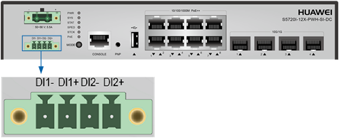

Monitoring interfaces must be used with phoenix terminals. Phoenix terminals are included in the auxiliary material package delivered with the switch. The minimum cross-sectional area of the conductor connected to a cable is 0.08 mm2 or 28 AWG, and the maximum cross-sectional area of the conductor is 1.5 mm2 or 16 AWG.
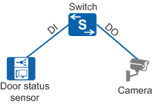
The S5735-S-I provides two monitoring interfaces, DI and DO, to monitor the status of the maintenance compartment door.
Connection Mode
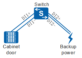
- S5720-SI
In Figure 2, high and low voltage output cables of the peer device are connected to the positive and negative interfaces (DI+ and DI-) of input lines of monitoring interfaces respectively. The switch monitors input level signals of the peer device to monitor the working status of the peer device. When the normal status of input lines of the monitoring interfaces is set to low level, the switch reports a trap to the NMS if high-level signals (9 V to 60 V) are detected. If low-level signals (0 V) are detected, the input lines are in normal state.
If the input status of a monitoring interface is abnormal, the switch generates traps. (Fault trap: MONITOR_1.3.6.1.4.1.2011.5.25.31.2.0.10 INPUTLINEABNORMAL. Clear trap: MONITOR_1.3.6.1.4.1.2011.5.25.31.2.0.11 INPUTLINENORMAL)
For example, monitoring interfaces can be used to monitor the cabinet door status. If the normal status of the input line of monitoring interfaces is set to low level, and the cabinet door is closed, the monitoring interfaces receive low-level signals of the corresponding line. When the cabinet door is opened, the monitoring interfaces receive high-level signals of the corresponding line and report a trap to the NMS.
- S5735-S-I
In Figure 3, the door status sensor is connected to the monitoring interface DI of the input line, and the camera is connected to the monitoring interface DO of the output line. You can monitor the status of the maintenance compartment door on a switch by checking the status of the monitoring function on the output line (DOUT status for short). If the initial DOUT status is configured to enabled, the DOUT status changes to disabled when the maintenance compartment door is opened, and changes to enabled when the maintenance compartment door is closed. Similarly, if the initial DOUT status is configured to disabled, the DOUT status changes to enabled when the maintenance compartment door is opened, and changes to disabled when the maintenance compartment door is closed. If the maintenance compartment door is opened, the monitoring interfaces report a trap to the NMS.
If the monitoring interfaces detect that the maintenance compartment door is opened, the switch generates traps. (Fault trap: ENTITYEXTTRAP_1.3.6.1.4.1.2011.5.25.219.2.2.40 hwBoardUpCoverAlarm. Clear trap: ENTITYEXTTRAP_1.3.6.1.4.1.2011.5.25.219.2.2.41 hwBoardUpCoverResume.)