Example for Configuring Synchronization Between LDP and IGP
Networking Requirements
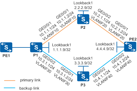
As shown in Figure 1, P1, P2, P3, and PE2 exist on the MPLS backbone network and OSPF runs between devices. Two LSPs are set up between PE1 and PE2 to transmit services: primary LSP (PE1 -> P1 -> P2 -> PE2) and backup LSP (PE1 -> P1 -> P3 -> PE2). After the primary link recovers, the IGP route of the primary link becomes active before an LDP session is established over the primary link. As a result, traffic is dropped during attempts to use the unreachable LSP. Short-time interruption of delay-sensitive services such as VoIP, online game, and online video service is unacceptable. It is required that the MPLS traffic loss be solved in this networking.

In this scenario, to avoid loops, ensure that all connected interfaces have STP disabled and connected interfaces are removed from VLAN 1. If STP is enabled and VLANIF interfaces of switches are used to construct a Layer 3 ring network, an interface on the network will be blocked. As a result, Layer 3 services on the network cannot run normally.
Configuration Roadmap
To meet the preceding requirements, configure synchronization between LDP and IGP. The configuration roadmap is as follows:
Configure OSPF on Ps and PE2 to implement IP connectivity on the backbone network.
Configure local LDP sessions on Ps and PE2 so that LDP LSPs can be set up to transmit network services.
Configure synchronization between LDP and IGP on P1 and P2 to prevent traffic loss.
Procedure
- Create VLANs and VLANIF interfaces on the switch, configure IP addresses
for the VLANIF interfaces, and add physical interfaces to the VLANs.
# Configure P1. The configurations of P2, P3, and PE2 are similar to the configuration of P1, and are not mentioned here.
<HUAWEI> system-view
[HUAWEI] sysname P1
[P1] interface loopback 1
[P1-LoopBack1] ip address 1.1.1.9 32
[P1-LoopBack1] quit
[P1] vlan batch 10 30
[P1] interface vlanif 10
[P1-Vlanif10] ip address 10.1.1.1 24
[P1-Vlanif10] quit
[P1] interface vlanif 30
[P1-Vlanif30] ip address 10.3.1.1 24
[P1-Vlanif30] quit
[P1] interface gigabitethernet 0/0/1
[P1-GigabitEthernet0/0/1] port link-type trunk
[P1-GigabitEthernet0/0/1] port trunk allow-pass vlan 10
[P1-GigabitEthernet0/0/1] quit
[P1] interface gigabitethernet 0/0/2
[P1-GigabitEthernet0/0/2] port link-type trunk
[P1-GigabitEthernet0/0/2] port trunk allow-pass vlan 30
[P1-GigabitEthernet0/0/2] quit
- Configure OSPF to advertise the network segments connecting
to interfaces on each node and to advertise the routes of hosts with
LSR IDs.
# Configure P1. The configurations of P2, P3, and PE2 are similar to the configuration of P1, and are not mentioned here.
[P1] ospf 1
[P1-ospf-1] area 0
[P1-ospf-1-area-0.0.0.0] network 1.1.1.9 0.0.0.0
[P1-ospf-1-area-0.0.0.0] network 10.1.1.0 0.0.0.255
[P1-ospf-1-area-0.0.0.0] network 10.3.1.0 0.0.0.255
[P1-ospf-1-area-0.0.0.0] quit
[P1-ospf-1] quit
- Set the cost of VLANIF 30 on P1 to 1000.
[P1] interface vlanif 30
[P1-Vlanif30] ospf cost 1000
[P1-Vlanif30] quit
After the configuration is complete, run the display ip routing-table command on each node. The command output shows that the nodes have learned routes from each other. The outbound interface of P1-to-PE2 route is VLANIF 10.
- Enable MPLS and MPLS LDP on each node and each interface.
# Configure P1.
[P1] mpls lsr-id 1.1.1.9
[P1] mpls
[P1-mpls] quit
[P1] mpls ldp
[P1-mpls-ldp] quit
[P1] interface vlanif 10
[P1-Vlanif10] mpls
[P1-Vlanif10] mpls ldp
[P1-Vlanif10] quit
[P1] interface vlanif 30
[P1-Vlanif30] mpls
[P1-Vlanif30] mpls ldp
[P1-Vlanif30] quit
# Configure P2.
[P2] mpls lsr-id 2.2.2.9
[P2] mpls
[P2-mpls] quit
[P2] mpls ldp
[P2-mpls-ldp] quit
[P2] interface vlanif 10
[P2-Vlanif10] mpls
[P2-Vlanif10] mpls ldp
[P2-Vlanif10] quit
[P2] interface vlanif 20
[P2-Vlanif20] mpls
[P2-Vlanif20] mpls ldp
[P2-Vlanif20] quit
# Configure P3.
[P3] mpls lsr-id 3.3.3.9
[P3] mpls
[P3-mpls] quit
[P3] mpls ldp
[P3-mpls-ldp] quit
[P3] interface vlanif 30
[P3-Vlanif30] mpls
[P3-Vlanif30] mpls ldp
[P3-Vlanif30] quit
[P3] interface vlanif 40
[P3-Vlanif40] mpls
[P3-Vlanif40] mpls ldp
[P3-Vlanif40] quit
# Configure PE2.
[PE2] mpls lsr-id 4.4.4.9
[PE2] mpls
[PE2-mpls] quit
[PE2] mpls ldp
[PE2-mpls-ldp] quit
[PE2] interface vlanif 20
[PE2-Vlanif20] mpls
[PE2-Vlanif20] mpls ldp
[PE2-Vlanif20] quit
[PE2] interface vlanif 40
[PE2-Vlanif40] mpls
[PE2-Vlanif40] mpls ldp
[PE2-Vlanif40] quit
After the configuration is complete, LDP sessions are established between neighboring nodes. Run the display mpls ldp session command on each node. The command output shows that the LDP session status is Operational. Use the display on P1 as an example.
[P1] display mpls ldp session

 LDP Session(s) in Public Network
 Codes: LAM(Label Advertisement Mode), SsnAge Unit(DDDD:HH:MM)
 A '*' before a session means the session is being deleted.
 ------------------------------------------------------------------------------
 PeerID             Status      LAM  SsnRole  SsnAge      KASent/Rcv
 ------------------------------------------------------------------------------
 2.2.2.9:0          Operational DU   Active   000:00:56   227/227
 3.3.3.9:0          Operational DU   Active   000:00:56   227/227
 ------------------------------------------------------------------------------
 TOTAL: 2 session(s) Found.
- Enable synchronization between LDP and IGP on the interfaces
at both ends of the link between P1 and P2.
# Configure P1.
[P1] interface vlanif 10
[P1-Vlanif10] ospf ldp-sync
[P1-Vlanif10] quit
# Configure P2.
[P2] interface vlanif 10
[P2-Vlanif10] ospf ldp-sync
[P2-Vlanif10] quit
- Set the value of Hold-down timer on the
interfaces at both ends of the link between P1 and P2.
# Configure P1.
[P1] interface vlanif 10
[P1-Vlanif10] ospf timer ldp-sync hold-down 8
[P1-Vlanif10] quit
# Configure P2.
[P2] interface vlanif 10
[P2-Vlanif10] ospf timer ldp-sync hold-down 8
[P2-Vlanif10] quit
- Set the value of Hold-max-cost timer on the interfaces
at both ends of the link between P1 and P2.
# Configure P1.
[P1] interface vlanif 10
[P1-Vlanif10] ospf timer ldp-sync hold-max-cost 9
[P1-Vlanif10] quit
# Configure P2.
[P2] interface vlanif 10
[P2-Vlanif10] ospf timer ldp-sync hold-max-cost 9
[P2-Vlanif10] quit
- Verify the configuration.
Run the display ospf ldp-sync command on P1. The command output shows that the interface status is Sync-Achieved.
[P1] display ospf ldp-sync interface vlanif 10
 Interface Vlanif10
 HoldDown Timer: 8         HoldMaxCost Timer: 9
 LDP State: Up             OSPF Sync State: Sync-Achieved
Configuration Files
P1 configuration file
#
sysname P1
#
vlan batch 10 30
#
mpls lsr-id 1.1.1.9
mpls
#
mpls ldp
#
interface Vlanif10
 ip address 10.1.1.1 255.255.255.0
 ospf ldp-sync
 ospf timer ldp-sync hold-down 8
 ospf timer ldp-sync hold-max-cost 9
 mpls
 mpls ldp
#
interface Vlanif30
 ip address 10.3.1.1 255.255.255.0
 ospf cost 1000
 mpls
 mpls ldp
#
interface GigabitEthernet0/0/1
 port link-type trunk
 port trunk allow-pass vlan 10
#
interface GigabitEthernet0/0/2
 port link-type trunk
 port trunk allow-pass vlan 30
#
interface LoopBack1
 ip address 1.1.1.9 255.255.255.255
#
ospf 1
 area 0.0.0.0
  network 1.1.1.9 0.0.0.0
  network 10.1.1.0 0.0.0.255
  network 10.3.1.0 0.0.0.255
#
return
P2 configuration file
#
sysname P2
#
vlan batch 10 20
#
mpls lsr-id 2.2.2.9
mpls
#
mpls ldp
#
interface Vlanif10
 ip address 10.1.1.2 255.255.255.0
 ospf ldp-sync
 ospf timer ldp-sync hold-down 8
 ospf timer ldp-sync hold-max-cost 9
 mpls
 mpls ldp
#
interface Vlanif20
 ip address 10.2.1.1 255.255.255.0
 mpls
 mpls ldp
#
interface GigabitEthernet0/0/1
 port link-type trunk
 port trunk allow-pass vlan 10
#
interface GigabitEthernet0/0/2
 port link-type trunk
 port trunk allow-pass vlan 20
#
interface LoopBack1
 ip address 2.2.2.9 255.255.255.255
#
ospf 1
 area 0.0.0.0
  network 2.2.2.9 0.0.0.0
  network 10.1.1.0 0.0.0.255
  network 10.2.1.0 0.0.0.255
#
return
P3 configuration file
#
sysname P3
#
vlan batch 30 40
#
mpls lsr-id 3.3.3.9
mpls
#
mpls ldp
#
interface Vlanif30
 ip address 10.3.1.2 255.255.255.0
 mpls
 mpls ldp
#
interface Vlanif40
 ip address 10.4.1.1 255.255.255.0
 mpls
 mpls ldp
#
interface GigabitEthernet0/0/1
 port link-type trunk
 port trunk allow-pass vlan 30
#
interface GigabitEthernet0/0/2
 port link-type trunk
 port trunk allow-pass vlan 40
#
interface LoopBack1
 ip address 3.3.3.9 255.255.255.255
#
ospf 1
 area 0.0.0.0
  network 3.3.3.9 0.0.0.0
  network 10.3.1.0 0.0.0.255
  network 10.4.1.0 0.0.0.255
#
return
PE2 configuration file
#
sysname PE2
#
vlan batch 20 40
#
mpls lsr-id 4.4.4.9
mpls
#
mpls ldp
#
interface Vlanif20
 ip address 10.2.1.2 255.255.255.0
 mpls
 mpls ldp
#
interface Vlanif40
 ip address 10.4.1.2 255.255.255.0
 mpls
 mpls ldp
#
interface GigabitEthernet0/0/1
 port link-type trunk
 port trunk allow-pass vlan 20
#
interface GigabitEthernet0/0/2
 port link-type trunk
 port trunk allow-pass vlan 40
#
interface LoopBack1
 ip address 4.4.4.9 255.255.255.255
#
ospf 1
 area 0.0.0.0
  network 4.4.4.9 0.0.0.0
  network 10.2.1.0 0.0.0.255
  network 10.4.1.0 0.0.0.255
#
return