Example for Configuring LDP GR
Networking Requirements
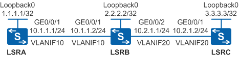
As shown in Figure 1, LSRA, LSRB, and LSRC are devices on the MPLS backbone network. Each of the three devices is a member in a stack, and it is required that services are not interrupted when an active/standby switchover occurs on LSRA, LSRB, and LSRC.
Configuration Roadmap
To meet the preceding requirements, configure LDP GR. The configuration roadmap is as follows:
- Configure OSPF on LSRs to implement IP connectivity on the backbone network.
- Configure local LDP sessions on LSRs so that LDP LSPs can be set up to transmit network services.
- Configure LDP GR on LSRs to prevent short-time traffic interruption.
Procedure
- Create VLANs and VLANIF interfaces on the switch, configure IP addresses
for the VLANIF interfaces, and add physical interfaces to the VLANs.
# Configure LSRA. The configurations of LSRB and LSRC are similar to the configuration of LSRA, and are not mentioned here.
<HUAWEI> system-view
[HUAWEI] sysname LSRA
[LSRA] interface loopback 0
[LSRA-LoopBack0] ip address 1.1.1.1 32
[LSRA-LoopBack0] quit
[LSRA] vlan batch 10
[LSRA] interface vlanif 10
[LSRA-Vlanif10] ip address 10.1.1.1 24
[LSRA-Vlanif10] quit
[LSRA] interface gigabitethernet 0/0/1
[LSRA-GigabitEthernet0/0/1] port link-type trunk
[LSRA-GigabitEthernet0/0/1] port trunk allow-pass vlan 10
[LSRA-GigabitEthernet0/0/1] quit
- Configure OSPF to advertise the network segments connecting
to interfaces on each node and to advertise the routes of hosts with
LSR IDs.
# Configure LSRA.
[LSRA] ospf 1
[LSRA-ospf-1] area 0
[LSRA-ospf-1-area-0.0.0.0] network 1.1.1.1 0.0.0.0
[LSRA-ospf-1-area-0.0.0.0] network 10.1.1.0 0.0.0.255
[LSRA-ospf-1-area-0.0.0.0] quit
[LSRA-ospf-1] quit
# Configure LSRB.
[LSRB] ospf 1
[LSRB-ospf-1] area 0
[LSRB-ospf-1-area-0.0.0.0] network 2.2.2.2 0.0.0.0
[LSRB-ospf-1-area-0.0.0.0] network 10.1.1.0 0.0.0.255
[LSRB-ospf-1-area-0.0.0.0] network 10.2.1.0 0.0.0.255
[LSRB-ospf-1-area-0.0.0.0] quit
[LSRB-ospf-1] quit
# Configure LSRC.
[LSRC] ospf 1
[LSRC-ospf-1] area 0
[LSRC-ospf-1-area-0.0.0.0] network 3.3.3.3 0.0.0.0
[LSRC-ospf-1-area-0.0.0.0] network 10.2.1.0 0.0.0.255
[LSRC-ospf-1-area-0.0.0.0] quit
[LSRC-ospf-1] quit
After the configuration is complete, run the display ip routing-table command on each node, and you can view that the nodes learn routes from each other.
- Configure OSPF GR.
# Configure LSRA.
[LSRA] ospf 1
[LSRA-ospf-1] opaque-capability enable
[LSRA-ospf-1] graceful-restart
[LSRA-ospf-1] quit
# Configure LSRB.
[LSRB] ospf 1
[LSRB-ospf-1] opaque-capability enable
[LSRB-ospf-1] graceful-restart
[LSRB-ospf-1] quit
# Configure LSRC.
[LSRC] ospf 1
[LSRC-ospf-1] opaque-capability enable
[LSRC-ospf-1] graceful-restart
[LSRC-ospf-1] quit
- Configure local LDP sessions.
# Configure LSRA. The configurations of LSRB and LSRC are similar to the configuration of LSRA, and are not mentioned here.
[LSRA] mpls lsr-id 1.1.1.1
[LSRA] mpls
[LSRA-mpls] quit
[LSRA] mpls ldp
[LSRA-mpls-ldp] quit
[LSRA] interface vlanif 10
[LSRA-Vlanif10] mpls
[LSRA-Vlanif10] mpls ldp
[LSRA-Vlanif10] quit
After the configuration is complete, local LDP sessions are established between LSRA and LSRB, and between LSRB and LSRC.
Run the display mpls ldp session command on each node to view the establishment of the LDP session. LSRA is used as an example.
[LSRA] display mpls ldp session

 LDP Session(s) in Public Network
 Codes: LAM(Label Advertisement Mode), SsnAge Unit(DDDD:HH:MM)
 A '*' before a session means the session is being deleted.
------------------------------------------------------------------------------
 PeerID             Status      LAM  SsnRole  SsnAge      KASent/Rcv
------------------------------------------------------------------------------
 2.2.2.2:0          Operational DU   Passive  0000:00:02   9/9
------------------------------------------------------------------------------
TOTAL: 1 session(s) Found.
- Configure LDP GR.
# Configure LSRA.
[LSRA] mpls ldp
[LSRA-mpls-ldp] graceful-restart
[LSRA-mpls-ldp] quit
# Configure LSRB.
[LSRB] mpls ldp
[LSRB-mpls-ldp] graceful-restart
[LSRB-mpls-ldp] quit
# Configure LSRC.
[LSRC] mpls ldp
[LSRC-mpls-ldp] graceful-restart
[LSRC-mpls-ldp] quit
- Verify the configuration.
# Run the display mpls ldp session verbose command on the LSRs. The command output shows that the Session FT Flag field is displayed as On. LSRA is used as an example.
[LSRA] display mpls ldp session verbose

               LDP Session(s) in Public Network
------------------------------------------------------------------------------
Peer LDP ID     : 2.2.2.2:0          Local LDP ID   : 1.1.1.1:0
TCP Connection  : 1.1.1.1 <- 2.2.2.2
Session State   : Operational        Session Role   : Passive
Session FT Flag : On                 MD5 Flag       : Off
Reconnect Timer : 300 Sec            Recovery Timer : 300 Sec
Keychain Name   : ---
Authentication applied : ---

Negotiated Keepalive Hold Timer   : 45 Sec
Configured Keepalive Send Timer   : ---
Keepalive Message Sent/Rcvd       : 4/4 (Message Count)
Label Advertisement Mode          : Downstream Unsolicited
Label Resource Status(Peer/Local) : Available/Available
Session Age                       : 0000:00:00 (DDDD:HH:MM)
Session Deletion Status           : No

Capability:
Capability-Announcement         : Off
mLDP P2MP Capability            : Off
mLDP MP2MP Capability           : Off
mLDP MBB Capability             : Off

Outbound&Inbound Policies applied : NULL

Addresses received from peer: (Count: 3)
2.2.2.2             10.1.1.2            10.2.1.1
------------------------------------------------------------------------------
# Or run the display mpls ldp peer verbose command on the LSRs. The command output shows that the Peer FT Flag field is displayed as On. LSRA is used as an example.
[LSRA] display mpls ldp peer verbose

 LDP Peer Information in Public network
 ------------------------------------------------------------------------------
 Peer LDP ID         : 2.2.2.2:0
 Peer Max PDU Length : 4096             Peer Transport Address : 2.2.2.2
 Peer Loop Detection : Off              Peer Path Vector Limit : ----
 Peer FT Flag        : On               Peer Keepalive Timer   : 45 Sec
 Recovery Timer      : 300 Sec          Reconnect Timer        : 300 Sec
 Peer Type           : Local

 Peer Label Advertisement Mode : Downstream Unsolicited
 Peer Discovery Source         : Vlanif10
 Peer Deletion Status          : No
 Capability-Announcement       : Off
 Peer mLDP P2MP Capability     : Off
 Peer mLDP MP2MP Capability    : Off
 Peer mLDP MBB Capability      : Off
 ------------------------------------------------------------------------------
Configuration Files
LSRA configuration file
#
sysname LSRA
#
vlan batch 10
#
mpls lsr-id 1.1.1.1
mpls
#
mpls ldp
 graceful-restart
#
interface Vlanif10
 ip address 10.1.1.1 255.255.255.0
 mpls
 mpls ldp
#
interface GigabitEthernet0/0/1
 port link-type trunk
 port trunk allow-pass vlan 10
#
interface LoopBack0
 ip address 1.1.1.1 255.255.255.255
#
ospf 1
 opaque-capability enable
 graceful-restart
 area 0.0.0.0
  network 1.1.1.1 0.0.0.0
  network 10.1.1.0 0.0.0.255
#
return
LSRB configuration file
#
sysname LSRB
#
vlan batch 10 20
#
mpls lsr-id 2.2.2.2
mpls
#
mpls ldp
 graceful-restart
#
interface Vlanif10
 ip address 10.1.1.2 255.255.255.0
 mpls
 mpls ldp
#
interface Vlanif20
 ip address 10.2.1.1 255.255.255.0
 mpls
 mpls ldp
#
interface GigabitEthernet0/0/1
 port link-type trunk
 port trunk allow-pass vlan 10
#
interface GigabitEthernet0/0/2
 port link-type trunk
 port trunk allow-pass vlan 20
#
interface LoopBack0
 ip address 2.2.2.2 255.255.255.255
#
ospf 1
 opaque-capability enable
 graceful-restart
 area 0.0.0.0
  network 2.2.2.2 0.0.0.0
  network 10.1.1.0 0.0.0.255
  network 10.2.1.0 0.0.0.255
#
return
LSRC configuration file
#
sysname LSRC
#
vlan batch 20
#
mpls lsr-id 3.3.3.3
mpls
#
mpls ldp
 graceful-restart
#
interface Vlanif20
 ip address 10.2.1.2 255.255.255.0
 mpls
 mpls ldp
#
interface GigabitEthernet0/0/1
 port link-type trunk
 port trunk allow-pass vlan 20
#
interface LoopBack0
 ip address 3.3.3.3 255.255.255.255
#
ospf 1
 opaque-capability enable
 graceful-restart
 area 0.0.0.0
  network 3.3.3.3 0.0.0.0
  network 10.2.1.0 0.0.0.255
#
return