Example for Configuring LDP Extension for Inter-Area LSP
Networking Requirements
On a large network, multiple IGP areas need to be configured for flexible network deployment and fast route convergence. When advertising routes between IGP areas, to prevent a large number of routes from consuming too many resources, an Area Border Router (ABR) needs to aggregate the routes in the area and advertises the aggregated route to the neighboring IGP areas. By default, when establishing LSPs, LDP searches the routing table for the route that exactly matches the FEC in the received Label Mapping message. If the route is an aggregated route, LDP establishes only a liberal LSP, not an inter-area LSP.
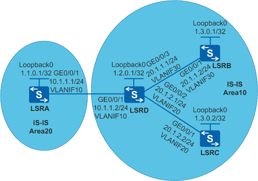
As shown in Figure 1, IS-IS runs between devices. Two IGP areas Area 10 and Area 20 exist. LSRD aggregates routes from LSRB and LSRC and sends the aggregated route to Area 20. Two inter-area LSPs need to be established: one is from LSRA to LSRB and the other is from LSRA to LSRC.
Configuration Roadmap
To meet the preceding requirements, configure LDP extension for inter-area LSP. The configuration roadmap is as follows:
- Configure IS-IS on LSRs to implement IP connectivity on the backbone network.
- Enable MPLS and MPLS LDP globally and interfaces of LSRs.
- Configure LDP extension for inter-area LSP on LSRA to enable LDP to search for a route according to the longest match rule to establish an LDP LSP.
Procedure
- On the switches, create VLANs and VLANIF interfaces, configure IP addresses for the VLANIF interfaces, and add physical interfaces to VLANs.
# Configure LSRA. The configurations of LSRB, LSRC, and LSRD are similar to the configuration of LSRA, and are not mentioned here.
<HUAWEI> system-view
[HUAWEI] sysname LSRA
[LSRA] interface loopback 0
[LSRA-LoopBack0] ip address 1.1.0.1 32
[LSRA-LoopBack0] quit
[LSRA] vlan batch 10
[LSRA] interface vlanif 10
[LSRA-Vlanif10] ip address 10.1.1.1 24
[LSRA-Vlanif10] quit
[LSRA] interface gigabitethernet 0/0/1
[LSRA-GigabitEthernet0/0/1] port link-type trunk
[LSRA-GigabitEthernet0/0/1] port trunk allow-pass vlan 10
[LSRA-GigabitEthernet0/0/1] quit
- Configure basic IS-IS functions.
# Configure LSRA.
[LSRA] isis 1
[LSRA-isis-1] is-level level-2
[LSRA-isis-1] network-entity 20.0010.0100.0001.00
[LSRA-isis-1] quit
[LSRA] interface vlanif 10
[LSRA-Vlanif10] isis enable 1
[LSRA-Vlanif10] quit
[LSRA] interface loopback 0
[LSRA-LoopBack0] isis enable 1
[LSRA-LoopBack0] quit
# Configure LSRD.
[LSRD] isis 1
[LSRD-isis-1] network-entity 10.0010.0200.0001.00
[LSRD-isis-1] quit
[LSRD] interface vlanif 10
[LSRD-Vlanif10] isis enable 1
[LSRD-Vlanif10] isis circuit-level level-2
[LSRD-Vlanif10] quit
[LSRD] interface vlanif 20
[LSRD-Vlanif20] isis enable 1
[LSRD-Vlanif20] isis circuit-level level-1
[LSRD-Vlanif20] quit
[LSRD] interface vlanif 30
[LSRD-Vlanif30] isis enable 1
[LSRD-Vlanif30] isis circuit-level level-1
[LSRD-Vlanif30] quit
[LSRD] interface loopback 0
[LSRD-LoopBack0] isis enable 1
[LSRD-LoopBack0] quit
# Configure LSRB.
[LSRB] isis 1
[LSRB-isis-1] is-level level-1
[LSRB-isis-1] network-entity 10.0010.0300.0001.00
[LSRB-isis-1] quit
[LSRB] interface vlanif 30
[LSRB-Vlanif30] isis enable 1
[LSRB-Vlanif30] quit
[LSRB] interface loopback 0
[LSRB-LoopBack0] isis enable 1
[LSRB-LoopBack0] quit
# Configure LSRC.
[LSRC] isis 1
[LSRC-isis-1] is-level level-1
[LSRC-isis-1] network-entity 10.0010.0300.0002.00
[LSRC-isis-1] quit
[LSRC] interface vlanif 20
[LSRC-Vlanif20] isis enable 1
[LSRC-Vlanif20] quit
[LSRC] interface loopback 0
[LSRC-LoopBack0] isis enable 1
[LSRC-LoopBack0] quit
# Run the display ip routing-table command on LSRA to check routing information.
[LSRA] display ip routing-table
Route Flags: R - relay, D - download to fib, T - to vpn-instance
------------------------------------------------------------------------------
Routing Tables: Public
         Destinations : 10       Routes : 10

Destination/Mask    Proto     Pre  Cost        Flags NextHop        Interface

        1.1.0.1/32  Direct    0    0             D  127.0.0.1       LoopBack0
        1.2.0.1/32  ISIS-L2   15   10            D  10.1.1.2        Vlanif10
        1.3.0.1/32  ISIS-L2   15   20            D  10.1.1.2        Vlanif10
        1.3.0.2/32  ISIS-L2   15   20            D  10.1.1.2        Vlanif10
       10.1.1.0/24  Direct    0    0             D  10.1.1.1        Vlanif10
       10.1.1.1/32  Direct    0    0             D  127.0.0.1       Vlanif10
       20.1.1.0/24  ISIS-L2   15   20            D  10.1.1.2        Vlanif10
       20.1.2.0/24  ISIS-L2   15   20            D  10.1.1.2        Vlanif10
      127.0.0.0/8   Direct    0    0             D  127.0.0.1       InLoopBack0
      127.0.0.1/32  Direct    0    0             D  127.0.0.1       InLoopBack0
- Configure a policy for generating the aggregated route.
# Run the summary command on LSRD to aggregate host routes that are destined for LSRB and LSRC.
[LSRD] isis 1
[LSRD-isis-1] summary 1.3.0.0 255.255.255.0 avoid-feedback
[LSRD-isis-1] quit
# Run the display ip routing-table command on LSRA to check routing information.
[LSRA] display ip routing-table
 Route Flags: R - relay, D - download to fib, T - to vpn-instance
 ------------------------------------------------------------------------------
 Routing Tables: Public
         Destinations : 9       Routes : 9

 Destination/Mask    Proto   Pre  Cost        Flags NextHop         Interface

        1.1.0.1/32  Direct    0    0             D  127.0.0.1       LoopBack0
        1.2.0.1/32  ISIS-L2   15   10            D  10.1.1.2        Vlanif10
        1.3.0.0/24  ISIS-L2   15   20            D  10.1.1.2        Vlanif10
       10.1.1.0/24  Direct    0    0             D  10.1.1.1        Vlanif10
       10.1.1.1/32  Direct    0    0             D  127.0.0.1       Vlanif10
       20.1.1.0/24  ISIS-L2   15   20            D  10.1.1.2        Vlanif10
       20.1.2.0/24  ISIS-L2   15   20            D  10.1.1.2        Vlanif10
      127.0.0.0/8   Direct    0    0             D  127.0.0.1       InLoopBack0
      127.0.0.1/32  Direct    0    0             D  127.0.0.1       InLoopBack0
The command output shows that host routes that are destined for LSRB and LSRC are aggregated.
- Configure global and interface-based MPLS and MPLS LDP on each node so that the network can forward MPLS traffic. Then check the LSP setup result.
# Configure LSRA.
[LSRA] mpls lsr-id 1.1.0.1
[LSRA] mpls
[LSRA-mpls] quit
[LSRA] mpls ldp
[LSRA-mpls-ldp] quit
[LSRA] interface vlanif 10
[LSRA-Vlanif10] mpls
[LSRA-Vlanif10] mpls ldp
[LSRA-Vlanif10] quit
# Configure LSRD.
[LSRD] mpls lsr-id 1.2.0.1
[LSRD] mpls
[LSRD-mpls] quit
[LSRD] mpls ldp
[LSRD-mpls-ldp] quit
[LSRD] interface vlanif 10
[LSRD-Vlanif10] mpls
[LSRD-Vlanif10] mpls ldp
[LSRD-Vlanif10] quit
[LSRD] interface vlanif 20
[LSRD-Vlanif20] mpls
[LSRD-Vlanif20] mpls ldp
[LSRD-Vlanif20] quit
[LSRD] interface vlanif 30
[LSRD-Vlanif30] mpls
[LSRD-Vlanif30] mpls ldp
[LSRD-Vlanif30] quit
# Configure LSRB.
[LSRB] mpls lsr-id 1.3.0.1
[LSRB] mpls
[LSRB-mpls] quit
[LSRB] mpls ldp
[LSRB-mpls-ldp] quit
[LSRB] interface vlanif 30
[LSRB-Vlanif30] mpls
[LSRB-Vlanif30] mpls ldp
[LSRB-Vlanif30] quit
# Configure LSRC.
[LSRC] mpls lsr-id 1.3.0.2
[LSRC] mpls
[LSRC-mpls] quit
[LSRC] mpls ldp
[LSRC-mpls-ldp] quit
[LSRC] interface vlanif 20
[LSRC-Vlanif20] mpls
[LSRC-Vlanif20] mpls ldp
[LSRC-Vlanif20] quit
# After the configuration is complete, run the display mpls lsp command on LSRA to view the established LSP.
[LSRA] display mpls lsp

Flag after Out IF: (I) - LSP Is Only Iterated by RLFA
-------------------------------------------------------------------------------
                 LSP Information: LDP LSP
-------------------------------------------------------------------------------
FEC                In/Out Label  In/Out IF                      Vrf Name
1.2.0.1/32         NULL/3        -/Vlanif10
1.2.0.1/32         1024/3        -/Vlanif10
1.1.0.1/32         3/NULL        -/-
The command output shows that by default, LDP does not establish the inter-area LSPs from LSRA to LSRB and from LSRA to LSRC.
- Configure LDP extensions for inter-area LSPs.
# Run the longest-match command on LSRA to configure LDP to search for a route according to the longest match rule to establish an inter-area LDP LSP.
[LSRA] mpls ldp
[LSRA-mpls-ldp] longest-match
[LSRA-mpls-ldp] quit
- Verify the configuration.
# Run the display mpls lsp command on LSRA to view the established LSP.
[LSRA] display mpls lsp

Flag after Out IF: (I) - LSP Is Only Iterated by RLFA
-------------------------------------------------------------------------------
                 LSP Information: LDP LSP
-------------------------------------------------------------------------------
FEC                In/Out Label  In/Out IF                      Vrf Name
1.2.0.1/32         NULL/3        -/Vlanif10
1.2.0.1/32         1024/3        -/Vlanif10
1.3.0.1/32         NULL/1025     -/Vlanif10
1.3.0.1/32         1025/1025     -/Vlanif10
1.3.0.2/32         NULL/1026     -/Vlanif10
1.3.0.2/32         1026/1026     -/Vlanif10
1.1.0.1/32         3/NULL        -/-
The command output shows that LDP establishes the inter-area LSPs from LSRA to LSRB and from LSRA to LSRC.
Configuration Files
LSRA configuration file
#
sysname LSRA
#
vlan batch 10
#
mpls lsr-id 1.1.0.1
mpls
#
mpls ldp
 longest-match
#
isis 1
 is-level level-2
 network-entity 20.0010.0100.0001.00
#
interface Vlanif10
 ip address 10.1.1.1 255.255.255.0
 isis enable 1
 mpls
 mpls ldp
#
interface GigabitEthernet0/0/1
 port link-type trunk
 port trunk allow-pass vlan 10
#
interface LoopBack0
 ip address 1.1.0.1 255.255.255.255
 isis enable 1
#
return
LSRD configuration file
#
sysname LSRD
#
vlan batch 10 20 30
#
mpls lsr-id 1.2.0.1
mpls
#
mpls ldp
#
isis 1
 network-entity 10.0010.0200.0001.00
 summary 1.3.0.0 255.255.255.0 avoid-feedback
#
interface Vlanif10
 ip address 10.1.1.2 255.255.255.0
 isis enable 1
 isis circuit-level level-2
 mpls
 mpls ldp
#
interface Vlanif20
 ip address 20.1.2.1 255.255.255.0
 isis enable 1
 isis circuit-level level-1
 mpls
 mpls ldp
#
interface Vlanif30
 ip address 20.1.1.1 255.255.255.0
 isis enable 1
 isis circuit-level level-1
 mpls
 mpls ldp
#
interface GigabitEthernet0/0/1
 port link-type trunk
 port trunk allow-pass vlan 10
#
interface GigabitEthernet0/0/3
 port link-type trunk
 port trunk allow-pass vlan 30
#
interface GigabitEthernet0/0/2
 port link-type trunk
 port trunk allow-pass vlan 20
#
interface LoopBack0
 ip address 1.2.0.1 255.255.255.255
 isis enable 1
#
return
LSRB configuration file
#
sysname LSRB
#
vlan batch 30
#
mpls lsr-id 1.3.0.1
mpls
#
mpls ldp
#
isis 1
 is-level level-1
 network-entity 10.0010.0300.0001.00
#
interface Vlanif30
 ip address 20.1.1.2 255.255.255.0
 isis enable 1
 mpls
 mpls ldp
#
interface GigabitEthernet0/0/1
 port link-type trunk
 port trunk allow-pass vlan 30
#
interface LoopBack0
 ip address 1.3.0.1 255.255.255.255
 isis enable 1
#
return
LSRC configuration file
#
sysname LSRC
#
vlan batch 20
#
mpls lsr-id 1.3.0.2
mpls
#
mpls ldp
#
isis 1
 is-level level-1
 network-entity 10.0010.0300.0002.00
#
interface Vlanif20
 ip address 20.1.2.2 255.255.255.0
 isis enable 1
 mpls
 mpls ldp
#
interface GigabitEthernet0/0/1
 port link-type trunk
 port trunk allow-pass vlan 20
#
interface LoopBack0
 ip address 1.3.0.2 255.255.255.255
 isis enable 1
#
return