Example for Configuring LDP GTSM
Networking Requirements
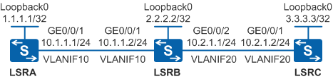
On an MPLS network shown in Figure 1, MPLS and MPLS LDP run between every two nodes. Attackers may simulate LDP unicast packets and send the packets to LSRB. LSRB becomes busy processing these packets, causing high CPU usage. The preceding problems need to be addressed to protect nodes and enhance system security.
Configuration Roadmap
To meet the preceding requirements, configure LDP GTSM. The configuration roadmap is as follows:
- Configure OSPF on LSRs to implement IP connectivity on the backbone network.
- Enable MPLS and MPLS LDP globally and interfaces of LSRs.
- Configure the LDP GTSM function on LSRs and set the TTL range.
Procedure
- Create VLANs and VLANIF interfaces on the switch, configure IP addresses for the VLANIF interfaces, and add physical interfaces to the VLANs.
# Configure LSRA. The configurations of LSRB and LSRC are similar to the configuration of LSRA, and are not mentioned here.
<HUAWEI> system-view
[HUAWEI] sysname LSRA
[LSRA] interface loopback 0
[LSRA-LoopBack0] ip address 1.1.1.1 32
[LSRA-LoopBack0] quit
[LSRA] vlan batch 10
[LSRA] interface vlanif 10
[LSRA-Vlanif10] ip address 10.1.1.1 24
[LSRA-Vlanif10] quit
[LSRA] interface gigabitethernet 0/0/1
[LSRA-GigabitEthernet0/0/1] port link-type trunk
[LSRA-GigabitEthernet0/0/1] port trunk allow-pass vlan 10
[LSRA-GigabitEthernet0/0/1] quit
- Configure OSPF to advertise the network segments connecting to interfaces on each node and to advertise the routes of hosts with LSR IDs.
# Configure LSRA.
[LSRA] ospf 1
[LSRA-ospf-1] area 0
[LSRA-ospf-1-area-0.0.0.0] network 1.1.1.1 0.0.0.0
[LSRA-ospf-1-area-0.0.0.0] network 10.1.1.0 0.0.0.255
[LSRA-ospf-1-area-0.0.0.0] quit
[LSRA-ospf-1] quit
# Configure LSRB.
[LSRB] ospf 1
[LSRB-ospf-1] area 0
[LSRB-ospf-1-area-0.0.0.0] network 2.2.2.2 0.0.0.0
[LSRB-ospf-1-area-0.0.0.0] network 10.1.1.0 0.0.0.255
[LSRB-ospf-1-area-0.0.0.0] network 10.2.1.0 0.0.0.255
[LSRB-ospf-1-area-0.0.0.0] quit
[LSRB-ospf-1] quit
# Configure LSRC.
[LSRC] ospf 1
[LSRC-ospf-1] area 0
[LSRC-ospf-1-area-0.0.0.0] network 3.3.3.3 0.0.0.0
[LSRC-ospf-1-area-0.0.0.0] network 10.2.1.0 0.0.0.255
[LSRC-ospf-1-area-0.0.0.0] quit
[LSRC-ospf-1] quit
After the configuration is complete, run the display ip routing-table command on each node, and you can view that the nodes learn routes from each other.
- Enable MPLS and MPLS LDP on each node and each interface of nodes.
# Configure LSRA. The configurations of LSRB and LSRC are similar to the configuration of LSRA, and are not mentioned here.
[LSRA] mpls lsr-id 1.1.1.1
[LSRA] mpls
[LSRA-mpls] quit
[LSRA] mpls ldp
[LSRA-mpls-ldp] quit
[LSRA] interface vlanif 10
[LSRA-Vlanif10] mpls
[LSRA-Vlanif10] mpls ldp
[LSRA-Vlanif10] quit
After the configuration is complete, run the display mpls ldp session command on each node to view the established LDP session. LSRA is used as an example.
[LSRA] display mpls ldp session
  LDP Session(s) in Public Network  Codes: LAM(Label Advertisement Mode), SsnAge Unit(DDDD:HH:MM)  A '*' before a session means the session is being deleted.
 ------------------------------------------------------------------------------
 PeerID             Status      LAM  SsnRole  SsnAge      KASent/Rcv
 ------------------------------------------------------------------------------
 2.2.2.2:0          Operational DU   Passive  0000:00:02  9/9
 ------------------------------------------------------------------------------
 TOTAL: 1 session(s) Found.
- Configure LDP GTSM.
# On LSRA, configure the TTL values carried in LDP packets received from LSRB to range from 253 to 255.
[LSRA] mpls ldp
[LSRA-mpls-ldp] gtsm peer 2.2.2.2 valid-ttl-hops 3
[LSRA-mpls-ldp] quit
# On LSRB, configure the TTL values carried in the LDP packets received from LSRA to range from 252 to 255, and the TTL values carried in LDP packets received from LSRC to range from 251 to 255.
[LSRB] mpls ldp
[LSRB-mpls-ldp] gtsm peer 1.1.1.1 valid-ttl-hops 4
[LSRB-mpls-ldp] gtsm peer 3.3.3.3 valid-ttl-hops 5
[LSRB-mpls-ldp] quit
# On LSRC, configure the TTL values carried in LDP packets received from LSRB to range from 250 to 255.
[LSRC] mpls ldp
[LSRC-mpls-ldp] gtsm peer 2.2.2.2 valid-ttl-hops 6
[LSRC-mpls-ldp] quit
If a host simulates the LDP packets of LSRA to attack LSRB, LSRB directly discards the packets because the TTL values carried in the LDP packets are beyond the range of 252 to 255. In the GTSM statistics on LSRB, the number of discarded packets increases.
Configuration Files
LSRA configuration file
#
sysname LSRA
#
vlan batch 10
#
mpls lsr-id 1.1.1.1
mpls
#
mpls ldp
 gtsm peer 2.2.2.2 valid-ttl-hops 3
#
interface Vlanif10
 ip address 10.1.1.1 255.255.255.0
 mpls
 mpls ldp
#
interface GigabitEthernet0/0/1
 port link-type trunk
 port trunk allow-pass vlan 10
#
interface LoopBack0
 ip address 1.1.1.1 255.255.255.255
#
ospf 1
 area 0.0.0.0
  network 1.1.1.1 0.0.0.0
  network 10.1.1.0 0.0.0.255
#
return
LSRB configuration file
#
sysname LSRB
#
vlan batch 10 20
#
mpls lsr-id 2.2.2.2
mpls
#
mpls ldp
 gtsm peer 1.1.1.1 valid-ttl-hops 4
 gtsm peer 3.3.3.3 valid-ttl-hops 5
#
interface Vlanif10
 ip address 10.1.1.2 255.255.255.0
 mpls
 mpls ldp
#
interface Vlanif20
 ip address 10.2.1.1 255.255.255.0
 mpls
 mpls ldp
#
interface GigabitEthernet0/0/1
 port link-type trunk
 port trunk allow-pass vlan 10
#
interface GigabitEthernet0/0/2
 port link-type trunk
 port trunk allow-pass vlan 20
#
interface LoopBack0
 ip address 2.2.2.2 255.255.255.255
#
ospf 1
 area 0.0.0.0
  network 2.2.2.2 0.0.0.0
  network 10.1.1.0 0.0.0.255
  network 10.2.1.0 0.0.0.255
#
return
LSRC configuration file
#
sysname LSRC
#
vlan batch 20
#
mpls lsr-id 3.3.3.3
mpls
#
mpls ldp
 gtsm peer 2.2.2.2 valid-ttl-hops 6
#
interface Vlanif20
 ip address 10.2.1.2 255.255.255.0
 mpls
 mpls ldp
#
interface GigabitEthernet0/0/1
 port link-type trunk
 port trunk allow-pass vlan 20
#
interface LoopBack0
 ip address 3.3.3.3 255.255.255.255
#
ospf 1
 area 0.0.0.0
  network 3.3.3.3 0.0.0.0
  network 10.2.1.0 0.0.0.255
#
return