Example for Configuring MPLS QoS (L3VPN)
Networking Requirements
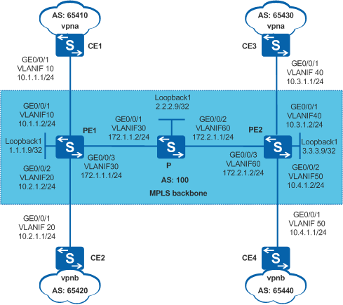
Enterprises A and B connect their headquarters to branches by deploying the BGP/MPLS IP VPN, as shown in Figure 1. CE1 and CE3 connect branches to the headquarters of Enterprise A, and CE2 and CE4 connect branches to the headquarters of Enterprise B. Enterprise A uses vpna and Enterprise B uses vpnb.
Enterprise A requires a higher service level, so better QoS must be provided for Enterprise A.
Configuration Roadmap
Configure MPLS QoS on PE1 and PE2. Enable the pipe mode on vpna and vpnb. Set the MPLS EXP values of vpna and vpnb to 4 and 3 respectively to provide better QoS guarantee for Enterprise A.
Procedure
- Configure OSPF on the MPLS backbone network so that PE
and P can communicate with each other.
# Configure PE1.
<HUAWEI> system-view
[HUAWEI] sysname PE1
[PE1] interface loopback 1
[PE1-LoopBack1] ip address 1.1.1.9 32
[PE1-LoopBack1] quit
[PE1] vlan batch 10 20 30
[PE1] interface gigabitethernet 0/0/1
[PE1-GigabitEthernet0/0/1] port link-type trunk
[PE1-GigabitEthernet0/0/1] port trunk allow-pass vlan 10
[PE1-GigabitEthernet0/0/1] quit
[PE1] interface gigabitethernet 0/0/2
[PE1-GigabitEthernet0/0/2] port link-type trunk
[PE1-GigabitEthernet0/0/2] port trunk allow-pass vlan 20
[PE1-GigabitEthernet0/0/2] quit
[PE1] interface gigabitethernet 0/0/3
[PE1-GigabitEthernet0/0/3] port link-type trunk
[PE1-GigabitEthernet0/0/3] port trunk allow-pass vlan 30
[PE1-GigabitEthernet0/0/3] quit
[PE1] interface vlanif 30
[PE1-Vlanif30] ip address 172.1.1.1 24
[PE1-Vlanif30] quit
[PE1] ospf 1
[PE1-ospf-1] area 0
[PE1-ospf-1-area-0.0.0.0] network 172.1.1.0 0.0.0.255
[PE1-ospf-1-area-0.0.0.0] network 1.1.1.9 0.0.0.0
[PE1-ospf-1-area-0.0.0.0] quit
[PE1-ospf-1] quit
# Configure P.
<HUAWEI> system-view
[HUAWEI] sysname P
[P] interface loopback 1
[P-LoopBack1] ip address 2.2.2.9 32
[P-LoopBack1] quit
[P] vlan batch 30 60
[P] interface gigabitethernet 0/0/1
[P-GigabitEthernet0/0/1] port link-type trunk
[P-GigabitEthernet0/0/1] port trunk allow-pass vlan 30
[P-GigabitEthernet0/0/1] quit
[P] interface gigabitethernet 0/0/2
[P-GigabitEthernet0/0/2] port link-type trunk
[P-GigabitEthernet0/0/2] port trunk allow-pass vlan 60
[P-GigabitEthernet0/0/2] quit
[P] interface vlanif 30
[P-Vlanif30] ip address 172.1.1.2 24
[P-Vlanif30] quit
[P] interface vlanif 60
[P-Vlanif60] ip address 172.2.1.1 24
[P-Vlanif60] quit
[P] ospf
[P-ospf-1] area 0
[P-ospf-1-area-0.0.0.0] network 172.1.1.0 0.0.0.255
[P-ospf-1-area-0.0.0.0] network 172.2.1.0 0.0.0.255
[P-ospf-1-area-0.0.0.0] network 2.2.2.9 0.0.0.0
[P-ospf-1-area-0.0.0.0] quit
[P-ospf-1] quit
# Configure PE2.
<HUAWEI> system-view
[HUAWEI] sysname PE2
[PE2] interface loopback 1
[PE2-LoopBack1] ip address 3.3.3.9 32
[PE2-LoopBack1] quit
[PE2] vlan batch 40 50 60
[PE2] interface gigabitethernet 0/0/1
[PE2-GigabitEthernet0/0/1] port link-type trunk
[PE2-GigabitEthernet0/0/1] port trunk allow-pass vlan 40
[PE2-GigabitEthernet0/0/1] quit
[PE2] interface gigabitethernet 0/0/2
[PE2-GigabitEthernet0/0/2] port link-type trunk
[PE2-GigabitEthernet0/0/2] port trunk allow-pass vlan 50
[PE2-GigabitEthernet0/0/2] quit
[PE2] interface gigabitethernet 0/0/3
[PE2-GigabitEthernet0/0/3] port link-type trunk
[PE2-GigabitEthernet0/0/3] port trunk allow-pass vlan 60
[PE2-GigabitEthernet0/0/3] quit
[PE2] interface vlanif 60
[PE2-Vlanif60] ip address 172.2.1.2 24
[PE2-Vlanif60] quit
[PE2] ospf
[PE2-ospf-1] area 0
[PE2-ospf-1-area-0.0.0.0] network 172.2.1.0 0.0.0.255
[PE2-ospf-1-area-0.0.0.0] network 3.3.3.9 0.0.0.0
[PE2-ospf-1-area-0.0.0.0] quit
[PE2-ospf-1] quit
After the configuration is complete, OSPF neighbor relationships are set up between PE1, P, and PE2. Run the display ip routing-table command. The command output shows that PEs have learned the routes to Loopback1 of each other.
- Configure basic MPLS functions, enable MPLS LDP, and establish
LDP LSPs on the MPLS backbone network.
# Configure PE1.
[PE1] mpls lsr-id 1.1.1.9
[PE1] mpls
[PE1-mpls] quit
[PE1] mpls ldp
[PE1-mpls-ldp] quit
[PE1] interface vlanif 30
[PE1-Vlanif30] mpls
[PE1-Vlanif30] mpls ldp
[PE1-Vlanif30] quit
# Configure P.
[P] mpls lsr-id 2.2.2.9
[P] mpls
[P-mpls] quit
[P] mpls ldp
[P-mpls-ldp] quit
[P] interface vlanif 30
[P-Vlanif30] mpls
[P-Vlanif30] mpls ldp
[P-Vlanif30] quit
[P] interface vlanif 60
[P-Vlanif60] mpls
[P-Vlanif60] mpls ldp
[P-Vlanif60] quit
# Configure PE2.
[PE2] mpls lsr-id 3.3.3.9
[PE2] mpls
[PE2-mpls] quit
[PE2] mpls ldp
[PE2-mpls-ldp] quit
[PE2] interface vlanif 60
[PE2-Vlanif60] mpls
[PE2-Vlanif60] mpls ldp
[PE2-Vlanif60] quit
After the configuration is complete, LDP sessions are set up between PE1 and P and between P and PE2. Run the display mpls ldp session command. The command output shows that the LDP session status is Operational.
PE1 is used as an example
[PE1] display mpls ldp session

 LDP Session(s) in Public Network
 Codes: LAM(Label Advertisement Mode), SsnAge Unit(DDDD:HH:MM)
 A '*' before a session means the session is being deleted.
 ------------------------------------------------------------------------------
 PeerID             Status      LAM  SsnRole  SsnAge      KASent/Rcv
 ------------------------------------------------------------------------------
 2.2.2.9:0          Operational DU   Active   0000:00:01  6/6
 ------------------------------------------------------------------------------
 TOTAL: 1 session(s) Found.
- Configure a VPN instance on each PE and connect the CEs
to the PEs.
# Configure PE1.
[PE1] ip vpn-instance vpna
[PE1-vpn-instance-vpna] ipv4-family
[PE1-vpn-instance-vpna-af-ipv4] route-distinguisher 100:1
[PE1-vpn-instance-vpna-af-ipv4] vpn-target 111:1 both
[PE1-vpn-instance-vpna-af-ipv4] quit
[PE1-vpn-instance-vpna] quit
[PE1] ip vpn-instance vpnb
[PE1-vpn-instance-vpnb] ipv4-family
[PE1-vpn-instance-vpnb-af-ipv4] route-distinguisher 100:2
[PE1-vpn-instance-vpnb-af-ipv4] vpn-target 222:2 both
[PE1-vpn-instance-vpnb-af-ipv4] quit
[PE1-vpn-instance-vpnb] quit
[PE1] interface vlanif 10
[PE1-Vlanif10] ip binding vpn-instance vpna
[PE1-Vlanif10] ip address 10.1.1.2 24
[PE1-Vlanif10] quit
[PE1] interface vlanif 20
[PE1-Vlanif20] ip binding vpn-instance vpnb
[PE1-Vlanif20] ip address 10.2.1.2 24
[PE1-Vlanif20] quit
# Configure PE2.
[PE2] ip vpn-instance vpna
[PE2-vpn-instance-vpna] ipv4-family
[PE2-vpn-instance-vpna-af-ipv4] route-distinguisher 200:1
[PE2-vpn-instance-vpna-af-ipv4] vpn-target 111:1 both
[PE2-vpn-instance-vpna-af-ipv4] quit
[PE2-vpn-instance-vpna] quit
[PE2] ip vpn-instance vpnb
[PE2-vpn-instance-vpnb] ipv4-family
[PE2-vpn-instance-vpnb-af-ipv4] route-distinguisher 200:2
[PE2-vpn-instance-vpnb-af-ipv4] vpn-target 222:2 both
[PE2-vpn-instance-vpnb-af-ipv4] quit
[PE2-vpn-instance-vpnb] quit
[PE2] interface vlanif 40
[PE2-Vlanif40] ip binding vpn-instance vpna
[PE2-Vlanif40] ip address 10.3.1.2 24
[PE2-Vlanif40] quit
[PE2] interface vlanif 50
[PE2-Vlanif50] ip binding vpn-instance vpnb
[PE2-Vlanif50] ip address 10.4.1.2 24
[PE2-Vlanif50] quit
# Assign IP addresses to the interfaces on the CEs according to Figure 1. The configuration procedure is not mentioned here.
After the configurations are complete, each PE can ping its connected CE.

If a PE has multiple interfaces bound to the same VPN instance, specify a source IP address by specifying -a source-ip-address in the ping -vpn-instance vpn-instance-name -a source-ip-address dest-ip-address command to ping the CE connected to the remote PE. If you do not specify a source IP address, the ping fails.
Use the command output on PE1 and CE1 as an example.
[PE1] ping -vpn-instance vpna 10.1.1.1 PING 10.1.1.1: 56 data bytes, press CTRL_C to break Reply from 10.1.1.1: bytes=56 Sequence=1 ttl=255 time=5 ms Reply from 10.1.1.1: bytes=56 Sequence=2 ttl=255 time=3 ms Reply from 10.1.1.1: bytes=56 Sequence=3 ttl=255 time=3 ms Reply from 10.1.1.1: bytes=56 Sequence=4 ttl=255 time=3 ms Reply from 10.1.1.1: bytes=56 Sequence=5 ttl=255 time=16 ms --- 10.1.1.1 ping statistics --- 5 packet(s) transmitted 5 packet(s) received 0.00% packet loss round-trip min/avg/max = 3/6/16 ms - Set up an MP-IBGP peer relationship between PEs.
# Configure PE1.
[PE1] bgp 100
[PE1-bgp] peer 3.3.3.9 as-number 100
[PE1-bgp] peer 3.3.3.9 connect-interface loopback 1
[PE1-bgp] ipv4-family vpnv4
[PE1-bgp-af-vpnv4] peer 3.3.3.9 enable
[PE1-bgp-af-vpnv4] quit
[PE1-bgp] quit
# Configure PE2.
[PE2] bgp 100
[PE2-bgp] peer 1.1.1.9 as-number 100
[PE2-bgp] peer 1.1.1.9 connect-interface loopback 1
[PE2-bgp] ipv4-family vpnv4
[PE2-bgp-af-vpnv4] peer 1.1.1.9 enable
[PE2-bgp-af-vpnv4] quit
[PE2-bgp] quit
After the configuration is complete, run the display bgp peer command on PEs. The command output shows that the BGP peer relationships have been established between the PEs.
[PE1] display bgp peer

 BGP local router ID : 1.1.1.9
 Local AS number : 100
 Total number of peers : 1                 Peers in established state : 1

  Peer            V    AS  MsgRcvd  MsgSent  OutQ  Up/Down       State              PrefRcv

  3.3.3.9         4   100       12        6     0 00:02:21        Established       0
- Set up the EBGP peer relationships between the PEs and
CEs and import VPN routes.
# Configure CE1.
[CE1] bgp 65410
[CE1-bgp] peer 10.1.1.2 as-number 100
[CE1-bgp] import-route direct
The configurations of CE2, CE3, and CE4 are similar to the configuration of CE1, and are not mentioned here.
# Configure PE1.
[PE1] bgp 100
[PE1-bgp] ipv4-family vpn-instance vpna
[PE1-bgp-vpna] peer 10.1.1.1 as-number 65410
[PE1-bgp-vpna] import-route direct
[PE1-bgp-vpna] quit
[PE1-bgp] ipv4-family vpn-instance vpnb
[PE1-bgp-vpnb] peer 10.2.1.1 as-number 65420
[PE1-bgp-vpnb] import-route direct
[PE1-bgp-vpnb] quit
[PE1-bgp] quit
The configuration of PE2 is similar to that of PE1, and is not mentioned here.
After the configurations are complete, run the display bgp vpnv4 vpn-instance peer command on the PEs. The command output shows that BGP peer relationships between PEs and CEs have been established.
Use the peer relationship between PE1 and CE1 as an example.
[PE1] display bgp vpnv4 vpn-instance vpna peer

 BGP local router ID : 1.1.1.9
 Local AS number : 100
 Total number of peers : 1                 Peers in established state : 1

  Peer            V    AS  MsgRcvd  MsgSent  OutQ  Up/Down       State      PrefRcv

  10.1.1.1        4 65410       11        9     0 00:07:25      Established       1
- Configure MPLS QoS.
#Configure PE1.
[PE1] mpls-qos ingress use vpn-label-exp
[PE1] ip vpn-instance vpna
[PE1-vpn-instance-vpna] diffserv-mode pipe mpls-exp 4
[PE1-vpn-instance-vpna] quit
[PE1] ip vpn-instance vpnb
[PE1-vpn-instance-vpnb] diffserv-mode pipe mpls-exp 3
[PE1-vpn-instance-vpnb] quit
#Configure PE2.
[PE2] mpls-qos ingress use vpn-label-exp
[PE2] ip vpn-instance vpna
[PE2-vpn-instance-vpna] diffserv-mode pipe mpls-exp 4
[PE2-vpn-instance-vpna] quit
[PE2] ip vpn-instance vpnb
[PE2-vpn-instance-vpnb] diffserv-mode pipe mpls-exp 3
[PE2-vpn-instance-vpnb] quit
After the configurations are complete, you must reset MPLS LDP and BGP connections to make the configuration take effect.
Configuration Files
PE1 configuration file
#
sysname PE1
#
vlan batch 10 20 30
#
mpls-qos ingress use vpn-label-exp
#
ip vpn-instance vpna
 ipv4-family
  route-distinguisher 100:1
  vpn-target 111:1 export-extcommunity
  vpn-target 111:1 import-extcommunity
  diffserv-mode pipe mpls-exp 4
#
ip vpn-instance vpnb
 ipv4-family
  route-distinguisher 100:2
  vpn-target 222:2 export-extcommunity
  vpn-target 222:2 import-extcommunity
  diffserv-mode pipe mpls-exp 3
#
mpls lsr-id 1.1.1.9
mpls
#
mpls ldp
#
interface Vlanif10
 ip binding vpn-instance vpna
 ip address 10.1.1.2 255.255.255.0
#
interface Vlanif20
 ip binding vpn-instance vpnb
 ip address 10.2.1.2 255.255.255.0
#
interface Vlanif30
 ip address 172.1.1.1 255.255.255.0
 mpls
 mpls ldp
#
interface GigabitEthernet0/0/1
 port link-type trunk
 port trunk allow-pass vlan 10
#
interface GigabitEthernet0/0/2
 port link-type trunk
 port trunk allow-pass vlan 20
#
interface GigabitEthernet0/0/3
 port link-type trunk
 port trunk allow-pass vlan 30
#
interface LoopBack1
 ip address 1.1.1.9 255.255.255.255
#
bgp 100
 peer 3.3.3.9 as-number 100
 peer 3.3.3.9 connect-interface LoopBack1
 #
 ipv4-family unicast
  undo synchronization
  peer 3.3.3.9 enable
 #
 ipv4-family vpnv4
  policy vpn-target
  peer 3.3.3.9 enable
 #
 ipv4-family vpn-instance vpna
  import-route direct
  peer 10.1.1.1 as-number 65410
 #
 ipv4-family vpn-instance vpnb
  import-route direct
  peer 10.2.1.1 as-number 65420
#
ospf 1
 area 0.0.0.0
  network 1.1.1.9 0.0.0.0
  network 172.1.1.0 0.0.0.255
#
return
P configuration file
#
sysname P
#
vlan batch 30 60
#
mpls lsr-id 2.2.2.9
mpls
#
mpls ldp
#
interface Vlanif30
 ip address 172.1.1.2 255.255.255.0
 mpls
 mpls ldp
#
interface Vlanif60
 ip address 172.2.1.1 255.255.255.0
 mpls
 mpls ldp
#
interface GigabitEthernet0/0/1
 port link-type trunk
 port trunk allow-pass vlan 30
#
interface GigabitEthernet0/0/2
 port link-type trunk
 port trunk allow-pass vlan 60
#
interface LoopBack1
 ip address 2.2.2.9 255.255.255.255
#
ospf 1
 area 0.0.0.0
  network 2.2.2.9 0.0.0.0
  network 172.1.1.0 0.0.0.255
  network 172.2.1.0 0.0.0.255
#
return
PE2 configuration file
#
sysname PE2
#
vlan batch 40 50 60
#
mpls-qos ingress use vpn-label-exp
#
ip vpn-instance vpna
 ipv4-family
  route-distinguisher 200:1
  vpn-target 111:1 export-extcommunity
  vpn-target 111:1 import-extcommunity
  diffserv-mode pipe mpls-exp 4
#
ip vpn-instance vpnb
 ipv4-family
  route-distinguisher 200:2
  vpn-target 222:2 export-extcommunity
  vpn-target 222:2 import-extcommunity
  diffserv-mode pipe mpls-exp 3
#
mpls lsr-id 3.3.3.9
mpls
#
mpls ldp
#
interface Vlanif40
 ip binding vpn-instance vpna
 ip address 10.3.1.2 255.255.255.0
#
interface Vlanif50
 ip binding vpn-instance vpnb
 ip address 10.4.1.2 255.255.255.0
#
interface Vlanif60
 ip address 172.2.1.2 255.255.255.0
 mpls
 mpls ldp
#
interface GigabitEthernet0/0/1
 port link-type trunk
 port trunk allow-pass vlan 40
#
interface GigabitEthernet0/0/2
 port link-type trunk
 port trunk allow-pass vlan 50
#
interface GigabitEthernet0/0/3
 port link-type trunk
 port trunk allow-pass vlan 60
#
interface LoopBack1
 ip address 3.3.3.9 255.255.255.255
#
bgp 100
 peer 1.1.1.9 as-number 100
 peer 1.1.1.9 connect-interface LoopBack1
 #
 ipv4-family unicast
  undo synchronization
  peer 1.1.1.9 enable
 #
 ipv4-family vpnv4
  policy vpn-target
  peer 1.1.1.9 enable
 #
 ipv4-family vpn-instance vpna
  import-route direct
  peer 10.3.1.1 as-number 65430
 #
 ipv4-family vpn-instance vpnb
  import-route direct
  peer 10.4.1.1 as-number 65440
#
ospf 1
 area 0.0.0.0
  network 3.3.3.9 0.0.0.0
  network 172.2.1.0 0.0.0.255
#
return
CE1 configuration file (enterprise A headquarters egress)
#
sysname CE1
#
vlan batch 10
#
interface Vlanif10
 ip address 10.1.1.1 255.255.255.0
#
interface GigabitEthernet0/0/1
 port link-type trunk
 port trunk allow-pass vlan 10
#
bgp 65410
 peer 10.1.1.2 as-number 100
 #
 ipv4-family unicast
  undo synchronization
  import-route direct
  peer 10.1.1.2 enable
#
return
CE2 configuration file (enterprise B headquarters egress)
#
sysname CE2
#
vlan batch 20
#
interface Vlanif20
 ip address 10.2.1.1 255.255.255.0
#
interface GigabitEthernet0/0/1
 port link-type trunk
 port trunk allow-pass vlan 20
#
bgp 65420
 peer 10.2.1.2 as-number 100
 #
 ipv4-family unicast
  undo synchronization
  import-route direct
  peer 10.2.1.2 enable
#
return
CE3 configuration file (enterprise A branch egress)
#
sysname CE3
#
vlan batch 40
#
interface Vlanif40
 ip address 10.3.1.1 255.255.255.0
#
interface GigabitEthernet0/0/1
 port link-type trunk
 port trunk allow-pass vlan 40
#
bgp 65430
 peer 10.3.1.2 as-number 100
 #
 ipv4-family unicast
  undo synchronization
  import-route direct
  peer 10.3.1.2 enable
#
return
CE4 configuration file (enterprise B branch egress)
#
sysname CE4
#
vlan batch 50
#
interface Vlanif50
 ip address 10.4.1.1 255.255.255.0
#
interface GigabitEthernet0/0/1
 port link-type trunk
 port trunk allow-pass vlan 50
#
bgp 65440
 peer 10.4.1.2 as-number 100
 #
 ipv4-family unicast
  undo synchronization
  import-route direct
  peer 10.4.1.2 enable
#
return