Example for Configuring MPLS QoS (L2VPN)
Networking Requirements
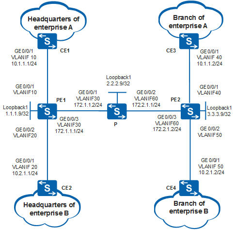
In Figure 1, CE1 and CE3 are connected to the headquarters and branch of enterprise A; CE2 and CE4 are connected to the headquarters and branch of enterprise B. Martini VLL is configured on PE1 and PE2 to enable communication between the headquarters and branch of the two enterprises separately.
It is required that better QoS guarantee be provided to enterprise A which as a higher service class.

By default, LNP is enabled globally on the device. If a VLANIF interface is used as an AC-side interface for L2VPN, the configuration conflicts with LNP. In this case, run the lnp disable command in the system view to disable LNP.
The lnp disable command has no impact on services before the device restarts. After the device restarts, the device can only forward packets from the VLANs specified by the port default vlan command at Layer 2. The port default vlan 1 command is configured by default, so only packets of VLAN 1 can be forwarded at Layer 2.
Configuration Roadmap
On the CEs, configure VLANs that interfaces belong to and IP addresses for VLANIF interfaces.
On PE1, the P, and PE2, configure an IGP routing protocol to implement interworking among the devices.
On PE1, the P, and PE2, configure basic MPLS functions and MPLS LDP to set up MPLS LSPs between these devices.
On PE1 and PE2, set up a remote LDP session to exchange VC labels between them.
On PE1 and PE2, configure MPLS QoS and configure the pipe mode. Set the MPLS EXP values to 4 and 3 for enterprises A and B, so that better QoS guarantee can be provided to enterprise A.
On PE1 and PE2, configure Martini VLL.
Procedure
- On the CEs, configure VLANs that interfaces belong to and IP addresses for VLANIF interfaces.
# Configure CE1. The configurations of CE2, CE3, and CE4 are similar to the configuration of CE1, and are not mentioned here.
<HUAWEI> system-view
[HUAWEI] sysname CE1
[CE1] vlan batch 10
[CE1] interface vlanif 10
[CE1-Vlanif10] ip address 10.1.1.1 255.255.255.0
[CE1-Vlanif10] quit
[CE1] interface gigabitethernet 0/0/1
[CE1-GigabitEthernet0/0/1] port link-type trunk
[CE1-GigabitEthernet0/0/1] port trunk allow-pass vlan 10
[CE1-GigabitEthernet0/0/1] quit
- Configure OSPF on the MPLS backbone network so that the PEs and P can communicate with each other.
# Configure PE1.
<HUAWEI> system-view
[HUAWEI] sysname PE1
[PE1] interface loopback 1
[PE1-LoopBack1] ip address 1.1.1.9 32
[PE1-LoopBack1] quit
[PE1] vlan batch 10 20 30
[PE1] interface gigabitethernet 0/0/1
[PE1-GigabitEthernet0/0/1] port link-type trunk
[PE1-GigabitEthernet0/0/1] port trunk allow-pass vlan 10
[PE1-GigabitEthernet0/0/1] quit
[PE1] interface gigabitethernet 0/0/2
[PE1-GigabitEthernet0/0/2] port link-type trunk
[PE1-GigabitEthernet0/0/2] port trunk allow-pass vlan 20
[PE1-GigabitEthernet0/0/2] quit
[PE1] interface gigabitethernet 0/0/3
[PE1-GigabitEthernet0/0/3] port link-type trunk
[PE1-GigabitEthernet0/0/3] port trunk allow-pass vlan 30
[PE1-GigabitEthernet0/0/3] quit
[PE1] interface vlanif 30
[PE1-Vlanif30] ip address 172.1.1.1 24
[PE1-Vlanif30] quit
[PE1] ospf 1
[PE1-ospf-1] area 0
[PE1-ospf-1-area-0.0.0.0] network 172.1.1.0 0.0.0.255
[PE1-ospf-1-area-0.0.0.0] network 1.1.1.9 0.0.0.0
[PE1-ospf-1-area-0.0.0.0] quit
[PE1-ospf-1] quit
# Configure the P.
<HUAWEI> system-view
[HUAWEI] sysname P
[P] interface loopback 1
[P-LoopBack1] ip address 2.2.2.9 32
[P-LoopBack1] quit
[P] vlan batch 30 60
[P] interface gigabitethernet 0/0/1
[P-GigabitEthernet0/0/1] port link-type trunk
[P-GigabitEthernet0/0/1] port trunk allow-pass vlan 30
[P-GigabitEthernet0/0/1] quit
[P] interface gigabitethernet 0/0/2
[P-GigabitEthernet0/0/2] port link-type trunk
[P-GigabitEthernet0/0/2] port trunk allow-pass vlan 60
[P-GigabitEthernet0/0/2] quit
[P] interface vlanif 30
[P-Vlanif30] ip address 172.1.1.2 24
[P-Vlanif30] quit
[P] interface vlanif 60
[P-Vlanif60] ip address 172.2.1.1 24
[P-Vlanif60] quit
[P] ospf
[P-ospf-1] area 0
[P-ospf-1-area-0.0.0.0] network 172.1.1.0 0.0.0.255
[P-ospf-1-area-0.0.0.0] network 172.2.1.0 0.0.0.255
[P-ospf-1-area-0.0.0.0] network 2.2.2.9 0.0.0.0
[P-ospf-1-area-0.0.0.0] quit
[P-ospf-1] quit
# Configure PE2.
<HUAWEI> system-view
[HUAWEI] sysname PE2
[PE2] interface loopback 1
[PE2-LoopBack1] ip address 3.3.3.9 32
[PE2-LoopBack1] quit
[PE2] vlan batch 40 50 60
[PE2] interface gigabitethernet 0/0/1
[PE2-GigabitEthernet0/0/1] port link-type trunk
[PE2-GigabitEthernet0/0/1] port trunk allow-pass vlan 40
[PE2-GigabitEthernet0/0/1] quit
[PE2] interface gigabitethernet 0/0/2
[PE2-GigabitEthernet0/0/2] port link-type trunk
[PE2-GigabitEthernet0/0/2] port trunk allow-pass vlan 50
[PE2-GigabitEthernet0/0/2] quit
[PE2] interface gigabitethernet 0/0/3
[PE2-GigabitEthernet0/0/3] port link-type trunk
[PE2-GigabitEthernet0/0/3] port trunk allow-pass vlan 60
[PE2-GigabitEthernet0/0/3] quit
[PE2] interface vlanif 60
[PE2-Vlanif60] ip address 172.2.1.2 24
[PE2-Vlanif60] quit
[PE2] ospf
[PE2-ospf-1] area 0
[PE2-ospf-1-area-0.0.0.0] network 172.2.1.0 0.0.0.255
[PE2-ospf-1-area-0.0.0.0] network 3.3.3.9 0.0.0.0
[PE2-ospf-1-area-0.0.0.0] quit
[PE2-ospf-1] quit
After the configuration is complete, OSPF neighbor relationships are set up between PE1, the P and PE2. Run the display ip routing-table command, and you can view that the PEs have learned the routes to Loopback1 from each other.
- Configure basic MPLS functions, enable MPLS LDP, and establish LDP LSPs on the MPLS backbone network.
# Configure PE1.
[PE1] mpls lsr-id 1.1.1.9
[PE1] mpls
[PE1-mpls] quit
[PE1] mpls ldp
[PE1-mpls-ldp] quit
[PE1] interface vlanif 30
[PE1-Vlanif30] mpls
[PE1-Vlanif30] mpls ldp
[PE1-Vlanif30] quit
# Configure the P.
[P] mpls lsr-id 2.2.2.9
[P] mpls
[P-mpls] quit
[P] mpls ldp
[P-mpls-ldp] quit
[P] interface vlanif 30
[P-Vlanif30] mpls
[P-Vlanif30] mpls ldp
[P-Vlanif30] quit
[P] interface vlanif 60
[P-Vlanif60] mpls
[P-Vlanif60] mpls ldp
[P-Vlanif60] quit
# Configure PE2.
[PE2] mpls lsr-id 3.3.3.9
[PE2] mpls
[PE2-mpls] quit
[PE2] mpls ldp
[PE2-mpls-ldp] quit
[PE2] interface vlanif 60
[PE2-Vlanif60] mpls
[PE2-Vlanif60] mpls ldp
[PE2-Vlanif60] quit
After the configuration is complete, PE1, the P, and PE2 set up LDP sessions. Run the display mpls ldp session command on PE1, P, and PE2, and you can view that the LDP session status is Operational. The display on PE1 is used as an example.
[PE1] display mpls ldp session

 LDP Session(s) in Public Network
 Codes: LAM(Label Advertisement Mode), SsnAge Unit(DDDD:HH:MM)
 A '*' before a session means the session is being deleted.
 ------------------------------------------------------------------------------
 PeerID             Status      LAM  SsnRole  SsnAge      KASent/Rcv
 ------------------------------------------------------------------------------
 2.2.2.9:0          Operational DU   Passive  0000:00:01  5/5
 ------------------------------------------------------------------------------
 TOTAL: 1 session(s) Found.
- Set up remote LDP sessions between the PEs.
# Configure PE1.
[PE1] mpls ldp remote-peer 3.3.3.9
[PE1-mpls-ldp-remote-3.3.3.9] remote-ip 3.3.3.9
[PE1-mpls-ldp-remote-3.3.3.9] quit
# Configure PE2.
[PE2] mpls ldp remote-peer 1.1.1.9
[PE2-mpls-ldp-remote-1.1.1.9] remote-ip 1.1.1.9
[PE2-mpls-ldp-remote-1.1.1.9] quit
After the configuration is complete, run the display mpls ldp session command on PE1 to view information about LDP sessions. The command output shows that two remote LDP sessions to PE2 have been established. The display on PE1 is used as an example.
[PE1] display mpls ldp session

 LDP Session(s) in Public Network
 Codes: LAM(Label Advertisement Mode), SsnAge Unit(DDDD:HH:MM)
 A '*' before a session means the session is being deleted.
 ------------------------------------------------------------------------------
 PeerID             Status      LAM  SsnRole  SsnAge      KASent/Rcv
 ------------------------------------------------------------------------------
 2.2.2.9:0          Operational DU   Passive  0000:00:09  40/40
 3.3.3.9:0          Operational DU   Passive  0000:00:09  37/37
 ------------------------------------------------------------------------------
 TOTAL: 2 session(s) Found.
- Configure MPLS QoS.
# Configure PE1.
[PE1] mpls-qos ingress use vpn-label-exp
[PE1] interface vlanif 10
[PE1-Vlanif10] diffserv-mode pipe mpls-exp 4
[PE1-Vlanif10] quit
[PE1] interface vlanif 20
[PE1-Vlanif20] diffserv-mode pipe mpls-exp 3
[PE1-Vlanif20] quit
# Configure PE2.
[PE2] mpls-qos ingress use vpn-label-exp
[PE2] interface vlanif 40
[PE2-Vlanif40] diffserv-mode pipe mpls-exp 4
[PE2-Vlanif40] quit
[PE2] interface vlanif 50
[PE2-Vlanif50] diffserv-mode pipe mpls-exp 3
[PE2-Vlanif50] quit
After the configuration is complete, run the reset mpls ldp command in the user view to make the configuration take effect.
- On the PEs, configure Martini VLL and create VC connections.
# On PE1, create a VC for VLANIF10 connecting to the CE1 interface, and a VC for VLANIF20 connecting to the CE2 interface. In this example, a VLANIF interface is used as the AC-side interface, so you need to run the lnp disable command in the system view before performing the following steps. If you cannot disable LNP on the live network, do not use a VLANIF interface as the AC-side interface.
[PE1] mpls l2vpn
[PE1-l2vpn] quit
[PE1] interface vlanif 10
[PE1-Vlanif10] mpls l2vc 3.3.3.9 101
[PE1-Vlanif10] quit
[PE1] interface vlanif 20
[PE1-Vlanif20] mpls l2vc 3.3.3.9 102
[PE1-Vlanif20] quit
# On PE2, create a VC for VLANIF40 connecting to the CE3 interface, and a VC for VLANIF50 connecting to the CE4 interface. In this example, a VLANIF interface is used as the AC-side interface, so you need to run the lnp disable command in the system view before performing the following steps. If you cannot disable LNP on the live network, do not use a VLANIF interface as the AC-side interface.
[PE2] mpls l2vpn
[PE2-l2vpn] quit
[PE2] interface vlanif 40
[PE2-Vlanif40] mpls l2vc 1.1.1.9 101
[PE2-Vlanif40] quit
[PE2] interface vlanif 50
[PE2-Vlanif50] mpls l2vc 1.1.1.9 102
[PE2-Vlanif50] quit
- Verify the configuration.
# Run the display mpls l2vc command on the PEs. You can view that two L2VCs in Up state are established and the DiffServ mode is pipe. The display on PE1 is used as an example.
[PE1] display mpls l2vc
 Total LDP VC : 2     2 up       0 down

 *client interface       : Vlanif10 is up
  Administrator PW       : no
  session state          : up
  AC status              : up
  Ignore AC state        : disable
  VC state               : up
  Label state            : 0
  Token state            : 0
  VC ID                  : 101
  VC type                : VLAN
  destination            : 3.3.3.9
  local VC label         : 1031         remote VC label      : 1030
  control word           : disable
  remote control word    : disable
  forwarding entry       : exist
  local group ID         : 0
  remote group ID        : 0
  local AC OAM State     : up
  local PSN OAM State    : up
  local forwarding state : forwarding
  local status code      : 0x0
  remote AC OAM state    : up
  remote PSN OAM state   : up
  remote forwarding state: forwarding
  remote status code     : 0x0
  ignore standby state   : no
  BFD for PW             : unavailable
  VCCV State             : up
  manual fault           : not set
  active state           : active
  link state             : up
  local VC MTU           : 1500         remote VC MTU        : 1500
  local VCCV             : alert ttl lsp-ping bfd
  remote VCCV            : alert ttl lsp-ping bfd
  tunnel policy name     : --
  PW template name       : --
  primary or secondary   : primary
  load balance type      : flow
  Access-port            : false
  Switchover Flag        : false
  VC tunnel/token info   : 1 tunnels/tokens
    NO.0  TNL type       : lsp   , TNL ID : 0x48000029
    Backup TNL type      : lsp   , TNL ID : 0x0
  create time            : 0 days, 3 hours, 26 minutes, 17 seconds
  up time                : 0 days, 0 hours, 26 minutes, 12 seconds
  last change time       : 0 days, 0 hours, 26 minutes, 12 seconds
  VC last up time        : 2017/10/17 19:02:05
  VC total up time       : 0 days, 3 hours, 23 minutes, 8 seconds
  CKey                   : 2
  NKey                   : 1
  PW redundancy mode     : frr
  AdminPw interface      : --
  AdminPw link state     : --
  Diffserv Mode          : pipe
  Service Class          : af4
  Color                  : --
  DomainId               : --
  Domain Name            : --

 *client interface       : Vlanif20 is up
  Administrator PW       : no
  session state          : up
  AC status              : up
  Ignore AC state        : disable
  VC state               : up
  Label state            : 0
  Token state            : 0
  VC ID                  : 102
  VC type                : VLAN
  destination            : 3.3.3.9
  local VC label         : 1032         remote VC label      : 1031
  control word           : disable
  remote control word    : disable
  forwarding entry       : exist
  local group ID         : 0
  remote group ID        : 0
  local AC OAM State     : up
  local PSN OAM State    : up
  local forwarding state : forwarding
  local status code      : 0x0
  remote AC OAM state    : up
  remote PSN OAM state   : up
  remote forwarding state: forwarding
  remote status code     : 0x0
  ignore standby state   : no
  BFD for PW             : unavailable
  VCCV State             : up
  manual fault           : not set
  active state           : active
  link state             : up
  local VC MTU           : 1500         remote VC MTU        : 1500
  local VCCV             : alert ttl lsp-ping bfd
  remote VCCV            : alert ttl lsp-ping bfd
  tunnel policy name     : --
  PW template name       : --
  primary or secondary   : primary
  load balance type      : flow
  Access-port            : false
  Switchover Flag        : false
  VC tunnel/token info   : 1 tunnels/tokens
    NO.0  TNL type       : lsp   , TNL ID : 0x48000029
    Backup TNL type      : lsp   , TNL ID : 0x0
  create time            : 0 days, 3 hours, 26 minutes, 0 seconds
  up time                : 0 days, 0 hours, 26 minutes, 16 seconds
  last change time       : 0 days, 0 hours, 26 minutes, 16 seconds
  VC last up time        : 2017/10/17 19:02:05
  VC total up time       : 0 days, 3 hours, 22 minutes, 48 seconds
  CKey                   : 3
  NKey                   : 1
  PW redundancy mode     : frr
  AdminPw interface      : --
  AdminPw link state     : --
  Diffserv Mode          : pipe
  Service Class          : af3
  Color                  : --
  DomainId               : --
  Domain Name            : --
# CE1 and CE3 can ping each other successfully. CE2 and CE4 can ping each other successfully. The display on CE1 is used as an example.
[CE1] ping 10.1.1.2
  PING 10.1.1.2: 56  data bytes, press CTRL_C to break
    Reply from 10.1.1.2: bytes=56 Sequence=1 ttl=254 time=1 ms
    Reply from 10.1.1.2: bytes=56 Sequence=2 ttl=254 time=1 ms
    Reply from 10.1.1.2: bytes=56 Sequence=3 ttl=254 time=1 ms
    Reply from 10.1.1.2: bytes=56 Sequence=4 ttl=254 time=1 ms
    Reply from 10.1.1.2: bytes=56 Sequence=5 ttl=254 time=1 ms

  --- 10.1.1.2 ping statistics ---
    5 packet(s) transmitted
    5 packet(s) received
    0.00% packet loss
    round-trip min/avg/max = 1/1/1 ms
Configuration Files
PE1 configuration file

The lnp disable command has no impact on services before the device restarts. After the device restarts, the device can only forward packets from the VLANs specified by the port default vlan command at Layer 2. The port default vlan 1 command is configured by default, so only packets of VLAN 1 can be forwarded at Layer 2.
#
sysname PE1
#
vlan batch 10 20 30
#
lnp disable
#
mpls lsr-id 1.1.1.9
mpls
#
mpls l2vpn
#
mpls ldp
#
mpls ldp remote-peer 3.3.3.9
 remote-ip 3.3.3.9
#
interface Vlanif10
 mpls l2vc 3.3.3.9 101
 diffserv-mode pipe mpls-exp 4
#
interface Vlanif20
 mpls l2vc 3.3.3.9 102
 diffserv-mode pipe mpls-exp 3
#
interface Vlanif30
 ip address 172.1.1.1 255.255.255.0
 mpls
 mpls ldp
#
interface GigabitEthernet0/0/1
 port link-type trunk
 port trunk allow-pass vlan 10
#
interface GigabitEthernet0/0/2
 port link-type trunk
 port trunk allow-pass vlan 20
#
interface GigabitEthernet0/0/3
 port link-type trunk
 port trunk allow-pass vlan 30
#
interface LoopBack1
 ip address 1.1.1.9 255.255.255.255
#
ospf 1
 area 0.0.0.0
  network 1.1.1.9 0.0.0.0
  network 172.1.1.0 0.0.0.255
#
mpls-qos ingress use vpn-label-exp
#
return
P configuration file
#
sysname P
#
vlan batch 30 60
#
mpls lsr-id 2.2.2.9
mpls
#
mpls ldp
#
interface Vlanif30
 ip address 172.1.1.2 255.255.255.0
 mpls
 mpls ldp
#
interface Vlanif60
 ip address 172.2.1.1 255.255.255.0
 mpls
 mpls ldp
#
interface GigabitEthernet0/0/1
 port link-type trunk
 port trunk allow-pass vlan 30
#
interface GigabitEthernet0/0/2
 port link-type trunk
 port trunk allow-pass vlan 60
#
interface LoopBack1
 ip address 2.2.2.9 255.255.255.255
#
ospf 1
 area 0.0.0.0
  network 2.2.2.9 0.0.0.0
  network 172.1.1.0 0.0.0.255
  network 172.2.1.0 0.0.0.255
#
return
PE2 configuration file
The lnp disable command has no impact on services before the device restarts. After the device restarts, the device can only forward packets from the VLANs specified by the port default vlan command at Layer 2. The port default vlan 1 command is configured by default, so only packets of VLAN 1 can be forwarded at Layer 2.
#
sysname PE2
#
vlan batch 40 50 60
#
lnp disable
#
mpls lsr-id 3.3.3.9
mpls
#
mpls l2vpn
#
mpls ldp
#
mpls ldp remote-peer 1.1.1.9
 remote-ip 1.1.1.9
#
interface Vlanif40
 mpls l2vc 1.1.1.9 101
 diffserv-mode pipe mpls-exp 4
#
interface Vlanif50
 mpls l2vc 1.1.1.9 102
 diffserv-mode pipe mpls-exp 3
#
interface Vlanif60
 ip address 172.2.1.2 255.255.255.0
 mpls
 mpls ldp
#
interface GigabitEthernet0/0/1
 port link-type trunk
 port trunk allow-pass vlan 40
#
interface GigabitEthernet0/0/2
 port link-type trunk
 port trunk allow-pass vlan 50
#
interface GigabitEthernet0/0/3
 port link-type trunk
 port trunk allow-pass vlan 60
#
interface LoopBack1
 ip address 3.3.3.9 255.255.255.255
#
ospf 1
 area 0.0.0.0
  network 3.3.3.9 0.0.0.0
  network 172.2.1.0 0.0.0.255
#
mpls-qos ingress use vpn-label-exp
#
return
CE1 configuration file
#
sysname CE1
#
vlan batch 10
#
interface Vlanif10
 ip address 10.1.1.1 255.255.255.0
#
interface GigabitEthernet0/0/1
 port link-type trunk
 port trunk allow-pass vlan 10
#
return
CE2 configuration file
#
sysname CE2
#
vlan batch 20
#
interface Vlanif20
 ip address 10.2.1.1 255.255.255.0
#
interface GigabitEthernet0/0/1
 port link-type trunk
 port trunk allow-pass vlan 20
#
return
CE3 configuration file
#
sysname CE3
#
vlan batch 40
#
interface Vlanif40
 ip address 10.1.1.2 255.255.255.0
#
interface GigabitEthernet0/0/1
 port link-type trunk
 port trunk allow-pass vlan 40
#
return
CE4 configuration file
#
sysname CE4
#
vlan batch 50
#
interface Vlanif50
 ip address 10.2.1.2 255.255.255.0
#
interface GigabitEthernet0/0/1
 port link-type trunk
 port trunk allow-pass vlan 50
#
return