Example for Configuring a Static MPLS TE Tunnel
Networking Requirements
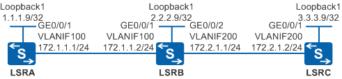
As shown in Figure 1, static TE tunnels from LSRA to LSRC and from LSRC to LSRA need to be set up.
Configuration Roadmap
The configuration roadmap is as follows:
Assign an IP address to each interface on each LSR and configure OSPF to ensure that there are reachable routes between LSRs.
Configure an ID for each LSR and globally enable MPLS and MPLS TE on each LSR and interface.
Create a tunnel interface on the ingress node and set the tunnel type to static CR-LSP.
Configure the static LSP bound to the tunnel; specify the next hop address and outgoing label on the ingress node; specify the inbound interface, incoming label, next hop address, and outgoing label on the transit node; specify the incoming label and inbound interface on the egress node.

The value of the outgoing label of each node is the value of the incoming label of its next node.
When running the static-cr-lsp ingress { tunnel-interface tunnel interface-number | tunnel-name } destination destination-address { nexthop next-hop-address | outgoing-interface interface-type interface-number } * out-label out-label command to configure the ingress node of a CR-LSP, ensure that tunnel-name must be the same as the tunnel name created by using the interface tunnel interface-number command. tunnel-name is a case-sensitive character string without spaces. For example, the name of the tunnel created by using the interface tunnel 1 command is Tunnel1. In this case, the parameter of the ingress node of the static CR-LSP is Tunnel1; otherwise, the tunnel cannot be created. There is no such limitation on the transit node and egress node.
Procedure
- Configure an IP address and routing protocol for each interface.
# Configure LSRA. Configure IP addresses for interfaces of LSRB and LSRC and OSPF according to Figure 1. The configurations of LSRB and LSRC are similar to the configuration of LSRA, and are not mentioned here.
<HUAWEI> system-view
[HUAWEI] sysname LSRA
[LSRA] vlan batch 100
[LSRA] interface vlanif 100
[LSRA-Vlanif100] ip address 172.1.1.1 255.255.255.0
[LSRA-Vlanif100] quit
[LSRA] interface gigabitethernet 0/0/1
[LSRA-GigabitEthernet0/0/1] port link-type trunk
[LSRA-GigabitEthernet0/0/1] port trunk allow-pass vlan 100
[LSRA-GigabitEthernet0/0/1] quit
[LSRA] interface loopback 1
[LSRA-LoopBack1] ip address 1.1.1.9 255.255.255.255
[LSRA-LoopBack1] quit
[LSRA] ospf 1
[LSRA-ospf-1] area 0
[LSRA-ospf-1-area-0.0.0.0] network 1.1.1.9 0.0.0.0
[LSRA-ospf-1-area-0.0.0.0] network 172.1.1.0 0.0.0.255
[LSRA-ospf-1-area-0.0.0.0] quit
[LSRA-ospf-1] quit
After the configurations are complete, OSPF neighbor relationships can be set up between LSRA, LSRB, and LSRC. Run the display ospf peer command. You can see that the neighbor status is Full. Run the display ip routing-table command. You can see that LSRs have learnt the routes to Loopback1 of each other.
- Configure basic MPLS functions and enable MPLS TE.
# Configure LSRA. The configurations of LSRB and LSRC are similar to the configuration of LSRA, and are not mentioned here.
[LSRA] mpls lsr-id 1.1.1.9
[LSRA] mpls
[LSRA-mpls] mpls te
[LSRA-mpls] quit
[LSRA] interface vlanif 100
[LSRA-Vlanif100] mpls
[LSRA-Vlanif100] mpls te
[LSRA-Vlanif100] quit
- Configure MPLS TE tunnels.
# On LSRA, create an MPLS TE tunnel from LSRA to LSRC.
[LSRA] interface tunnel 1
[LSRA-Tunnel1] ip address unnumbered interface loopback 1
[LSRA-Tunnel1] tunnel-protocol mpls te
[LSRA-Tunnel1] destination 3.3.3.9
[LSRA-Tunnel1] mpls te tunnel-id 100
[LSRA-Tunnel1] mpls te signal-protocol cr-static
[LSRA-Tunnel1] mpls te commit
[LSRA-Tunnel1] quit
# On LSRC, create an MPLS TE tunnel from LSRC to LSRA.
[LSRC] interface tunnel 1
[LSRC-Tunnel1] ip address unnumbered interface loopback 1
[LSRC-Tunnel1] tunnel-protocol mpls te
[LSRC-Tunnel1] destination 1.1.1.9
[LSRC-Tunnel1] mpls te tunnel-id 200
[LSRC-Tunnel1] mpls te signal-protocol cr-static
[LSRC-Tunnel1] mpls te commit
[LSRC-Tunnel1] quit
- Create a static CR-LSP from LSRA to LSRC.
# Configure LSRA as the ingress node of the static CR-LSP.
[LSRA] static-cr-lsp ingress tunnel-interface Tunnel1 destination 3.3.3.9 nexthop 172.1.1.2 out-label 20# Configure LSRB as the transit node of the static CR-LSP.
[LSRB] static-cr-lsp transit LSRA2LSRC incoming-interface vlanif 100 in-label 20 nexthop 172.2.1.2 out-label 30
# Configure LSRC as the egress node of the static CR-LSP.
[LSRC] static-cr-lsp egress LSRA2LSRC incoming-interface vlanif 200 in-label 30
- Create a static CR-LSP from LSRC to LSRA.
# Configure LSRC as the ingress node of the static CR-LSP.
[LSRC] static-cr-lsp ingress tunnel-interface Tunnel1 destination 1.1.1.9 nexthop 172.2.1.1 out-label 120# Configure LSRB as the transit node of the static CR-LSP.
[LSRB] static-cr-lsp transit LSRC2LSRA incoming-interface vlanif 200 in-label 120 nexthop 172.1.1.1 out-label 130
# Configure LSRA as the egress node of the static CR-LSP.
[LSRA] static-cr-lsp egress LSRC2LSRA incoming-interface vlanif 100 in-label 130
- Verify the configuration.
After the configurations are complete, run the display interface tunnel command on LSRA. You can see that the tunnel interface status is Up.
The display on LSRA is used as an example.
[LSRA] display interface tunnel 1
Tunnel1 current state : UP
Line protocol current state : UP
...
Run the display mpls te tunnel command on each LSR to view the MPLS TE tunnel status.
The display on LSRA is used as an example.
[LSRA] display mpls te tunnel
------------------------------------------------------------------------------
Ingress LsrId    Destination      LSPID   In/Out Label     R  Tunnel-name
------------------------------------------------------------------------------
1.1.1.9          3.3.3.9          1       --/20            I  Tunnel1
-                -                -       130/--           E  LSRC2LSRA
Run the display mpls lsp or display mpls static-cr-lsp command on each LSR to view the static CR-LSP status.
The display on LSRA is used as an example.
[LSRA] display mpls static-cr-lsp
TOTAL          : 2     STATIC CRLSP(S)
UP             : 2     STATIC CRLSP(S)
DOWN           : 0     STATIC CRLSP(S)
Name                FEC                I/O Label    I/O If                Status
Tunnel1             3.3.3.9/32         NULL/20      -/Vlanif100           Up
LSRC2LSRA           -/-                130/NULL     Vlanif100/-           Up
When a static CR-LSP is used to establish an MPLS TE tunnel, the transit node and the egress node do not forward packets according to the specified incoming label and outgoing label. Therefore, no EFC information is displayed on LSRB or LSRC.
Configuration Files
LSRA configuration file
#
sysname LSRA
#
vlan batch 100
#
mpls lsr-id 1.1.1.9
mpls
 mpls te
#
interface Vlanif100
 ip address 172.1.1.1 255.255.255.0
 mpls
 mpls te
#
interface GigabitEthernet0/0/1
 port link-type trunk
 port trunk allow-pass vlan 100
#
interface LoopBack1
 ip address 1.1.1.9 255.255.255.255
#
interface Tunnel1
 ip address unnumbered interface LoopBack1
 tunnel-protocol mpls te
 destination 3.3.3.9
 mpls te signal-protocol cr-static
 mpls te tunnel-id 100
 mpls te commit
#
ospf 1
 area 0.0.0.0
  network 1.1.1.9 0.0.0.0
  network 172.1.1.0 0.0.0.255
#
static-cr-lsp ingress tunnel-interface Tunnel1 destination 3.3.3.9 nexthop 172.1.1.2 out-label 20 bandwidth ct0 0
static-cr-lsp egress LSRC2LSRA incoming-interface Vlanif100 in-label 130
#
return
LSRB configuration file
#
sysname LSRB
#
vlan batch 100 200
#
mpls lsr-id 2.2.2.9
mpls
 mpls te
#
interface Vlanif100
 ip address 172.1.1.2 255.255.255.0
 mpls
 mpls te
#
interface Vlanif200
 ip address 172.2.1.1 255.255.255.0
 mpls
 mpls te
#
interface GigabitEthernet0/0/1
 port link-type trunk
 port trunk allow-pass vlan 100
#
interface GigabitEthernet0/0/2
 port link-type trunk
 port trunk allow-pass vlan 200
#
interface LoopBack1
 ip address 2.2.2.9 255.255.255.255
#
ospf 1
 area 0.0.0.0
  network 2.2.2.9 0.0.0.0
  network 172.1.1.0 0.0.0.255
  network 172.2.1.0 0.0.0.255
#
static-cr-lsp transit LSRA2LSRC incoming-interface Vlanif100 in-label 20 nexthop 172.2.1.2 out-label 30 bandwidth ct0 0
static-cr-lsp transit LSRC2LSRA incoming-interface Vlanif200 in-label 120 nexthop 172.1.1.1 out-label 130 bandwidth ct0 0
#
return
LSRC configuration file
#
sysname LSRC
#
vlan batch 200
#
mpls lsr-id 3.3.3.9
mpls
 mpls te
#
interface Vlanif200
 ip address 172.2.1.2 255.255.255.0
 mpls
 mpls te
#
interface GigabitEthernet0/0/1
 port link-type trunk
 port trunk allow-pass vlan 200
#
interface LoopBack1
 ip address 3.3.3.9 255.255.255.255
#
interface Tunnel1
 ip address unnumbered interface LoopBack1
 tunnel-protocol mpls te
 destination 1.1.1.9
 mpls te signal-protocol cr-static
 mpls te tunnel-id 200
 mpls te commit
#
ospf 1
 area 0.0.0.0
  network 3.3.3.9 0.0.0.0
  network 172.2.1.0 0.0.0.255
#
static-cr-lsp egress LSRA2LSRC incoming-interface Vlanif200 in-label 30
static-cr-lsp ingress tunnel-interface Tunnel1 destination 1.1.1.9 nexthop 172.2.1.1 out-label 120 bandwidth ct0 0
#
return