Example for Configuring a Dynamic MPLS TE Tunnel
Networking Requirements
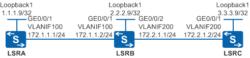
As shown in Figure 1, an enterprise establishes its own MPLS backbone network with LSRA, LSRB, and LSRC deployed. The MPLS backbone network uses IS-IS, and LSRA, LSRB, and LSRC are level-2 devices. A tunnel needs to be set up over the public network on the MPLS backbone network to transmit L2VPN or L3VPN services, and the tunnel must be able to adapt to network topology changes to ensure stable data transmission.
RSVP-TE is used to establish a dynamic MPLS TE tunnel.
Configuration Roadmap
The configuration roadmap is as follows:
On the MPLS backbone network, MPLS LDP and MPLS TE tunnels can carry L2VPN or L3VPN services. Configure an MPLS TE tunnel to ensure stable data transmission upon frequent topology changes on the enterprise network.
Configure IS-IS to ensure that there are reachable routes between devices on the MPLS backbone network.
Enable MPLS TE and RSVP-TE on each node so that an MPLS TE tunnel can be set up.
Enable IS-IS TE and change the cost type so that TE information can be advertised to other nodes through IS-IS.
Create a tunnel interface on the ingress node, configure tunnel attributes, and enable MPLS TE CSPF to create a dynamic MPLS TE tunnel.
Procedure
- Assign IP addresses to interfaces.
# Configure LSRA. Configure IP addresses for interfaces of LSRB and LSRC according to Figure 1. The configurations of LSRB and LSRC are similar to the configuration of LSRA, and are not mentioned here.
<HUAWEI> system-view
[HUAWEI] sysname LSRA
[LSRA] vlan batch 100
[LSRA] interface vlanif 100
[LSRA-Vlanif100] ip address 172.1.1.1 255.255.255.0
[LSRA-Vlanif100] quit
[LSRA] interface gigabitethernet 0/0/1
[LSRA-GigabitEthernet0/0/1] port link-type trunk
[LSRA-GigabitEthernet0/0/1] port trunk allow-pass vlan 100
[LSRA-GigabitEthernet0/0/1] quit
[LSRA] interface loopback 1
[LSRA-LoopBack1] ip address 1.1.1.9 255.255.255.255
[LSRA-LoopBack1] quit
- Configure IS-IS to advertise routes.
# Configure LSRA.
[LSRA] isis 1
[LSRA-isis-1] network-entity 00.0005.0000.0000.0001.00
[LSRA-isis-1] is-level level-2
[LSRA-isis-1] quit
[LSRA] interface vlanif 100
[LSRA-Vlanif100] isis enable 1
[LSRA-Vlanif100] quit
[LSRA] interface loopback 1
[LSRA-LoopBack1] isis enable 1
[LSRA-LoopBack1] quit
# Configure LSRB.
[LSRB] isis 1
[LSRB-isis-1] network-entity 00.0005.0000.0000.0002.00
[LSRB-isis-1] is-level level-2
[LSRB-isis-1] quit
[LSRB] interface vlanif 100
[LSRB-Vlanif100] isis enable 1
[LSRB-Vlanif100] quit
[LSRB] interface vlanif 200
[LSRB-Vlanif200] isis enable 1
[LSRB-Vlanif200] quit
[LSRB] interface loopback 1
[LSRB-LoopBack1] isis enable 1
[LSRB-LoopBack1] quit
# Configure LSRC.
[LSRC] isis 1
[LSRC-isis-1] network-entity 00.0005.0000.0000.0003.00
[LSRC-isis-1] is-level level-2
[LSRC-isis-1] quit
[LSRC] interface vlanif 200
[LSRC-Vlanif200] isis enable 1
[LSRC-Vlanif200] quit
[LSRC] interface loopback 1
[LSRC-LoopBack1] isis enable 1
[LSRC-LoopBack1] quit
After the configurations are complete, run the display ip routing-table command on each LSR. You can see that the LSRs have learned the routes from each other. The display on LSRA is used as an example.
[LSRA] display ip routing-table Route Flags: R - relay, D - download to fib, T - to vpn-instance ------------------------------------------------------------------------------ Routing Tables: Public Destinations : 8 Routes : 8 Destination/Mask Proto Pre Cost Flags NextHop Interface 1.1.1.9/32 Direct 0 0 D 127.0.0.1 LoopBack1 2.2.2.9/32 ISIS-L2 15 10 D 172.1.1.2 Vlanif100 3.3.3.9/32 ISIS-L2 15 20 D 172.1.1.2 Vlanif100 127.0.0.0/8 Direct 0 0 D 127.0.0.1 InLoopBack0 127.0.0.1/32 Direct 0 0 D 127.0.0.1 InLoopBack0 172.1.1.0/24 Direct 0 0 D 172.1.1.1 Vlanif100 172.1.1.1/32 Direct 0 0 D 127.0.0.1 Vlanif100 172.2.1.0/24 ISIS-L2 15 20 D 172.1.1.2 Vlanif100 - Configure basic MPLS functions and enable MPLS TE and RSVP-TE.
Enable MPLS, MPLS TE, and RSVP-TE globally on each node and interfaces along the tunnel.
# Configure LSRA. The configurations of LSRB and LSRC are similar to the configuration of LSRA, and are not mentioned here.
[LSRA] mpls lsr-id 1.1.1.9
[LSRA] mpls
[LSRA-mpls] mpls te
[LSRA-mpls] mpls rsvp-te
[LSRA-mpls] quit
[LSRA] interface vlanif 100
[LSRA-Vlanif100] mpls
[LSRA-Vlanif100] mpls te
[LSRA-Vlanif100] mpls rsvp-te
[LSRA-Vlanif100] quit
- Configure IS-IS TE.
# Configure LSRA. The configurations of LSRB and LSRC are similar to the configuration of LSRA, and are not mentioned here.
[LSRA] isis 1
[LSRA-isis-1] cost-style wide
[LSRA-isis-1] traffic-eng level-2
[LSRA-isis-1] quit
- Configure an MPLS TE tunnel interface and enable MPLS TE CSPF.
# On the ingress node of the tunnel, create a tunnel interface, and set the IP address, tunnel protocol, destination IP address, tunnel ID, and dynamic signaling protocol for the tunnel interface. Then run the mpls te commit command to commit the configuration.
# Configure LSRA.
[LSRA] interface tunnel 1
[LSRA-Tunnel1] ip address unnumbered interface loopback 1
[LSRA-Tunnel1] tunnel-protocol mpls te
[LSRA-Tunnel1] destination 3.3.3.9
[LSRA-Tunnel1] mpls te tunnel-id 100
[LSRA-Tunnel1] mpls te signal-protocol rsvp-te
[LSRA-Tunnel1] mpls te commit
[LSRA-Tunnel1] quit
[LSRA] mpls
[LSRA-mpls] mpls te cspf
[LSRA-mpls] quit
- Verify the configuration.
After the configurations are complete, run the display interface tunnel command on LSRA. You can see that the tunnel interface status is Up.
[LSRA] display interface tunnel
Tunnel1 current state : UP
Line protocol current state : UP
Last line protocol up time : 2013-01-14 09:18:46
Description:
...
Run the display mpls te tunnel-interface command on LSRA. You can view tunnel interface information.
[LSRA] display mpls te tunnel-interface
    ----------------------------------------------------------------
                               Tunnel1
    ----------------------------------------------------------------
    Tunnel State Desc   :  UP
    Active LSP          :  Primary LSP
    Session ID          :  100
    Ingress LSR ID      :  1.1.1.9          Egress LSR ID:  3.3.3.9
    Admin State         :  UP               Oper State   :  UP
    Primary LSP State      : UP
      Main LSP State       : READY               LSP ID  : 3
Run the display mpls te tunnel verbose command on LSRA. You can view detailed information about the tunnel.
[LSRA] display mpls te tunnel verbose
    No                      :  1
    Tunnel-Name             :  Tunnel1
    Tunnel Interface Name   :  Tunnel1
    TunnelIndex             :  1           LSP Index         :  2048
    Session ID              :  100         LSP ID            :  3
    LSR Role                :  Ingress     LSP Type          :  Primary
    Ingress LSR ID          :  1.1.1.9
    Egress LSR ID           :  3.3.3.9
    In-Interface            :  -
    Out-Interface           :  Vlanif100
    Sign-Protocol           :  RSVP TE     Resv Style        :  SE
    IncludeAnyAff           :  0x0         ExcludeAnyAff     :  0x0
    IncludeAllAff           :  0x0
    LspConstraint           :  -
    ER-Hop Table Index      :  -           AR-Hop Table Index:  -
    C-Hop Table Index       :  -
    PrevTunnelIndexInSession:  -           NextTunnelIndexInSession:  -
    PSB Handle              :  16388
    Created Time            :  2013-09-16 11:51:21+00:00
    RSVP LSP Type           :  -
    --------------------------------
              DS-TE Information
    --------------------------------
    Bandwidth Reserved Flag :  Unreserved
    CT0 Bandwidth(Kbit/sec) :  0           CT1 Bandwidth(Kbit/sec):  0
    CT2 Bandwidth(Kbit/sec) :  0           CT3 Bandwidth(Kbit/sec):  0
    CT4 Bandwidth(Kbit/sec) :  0           CT5 Bandwidth(Kbit/sec):  0
    CT6 Bandwidth(Kbit/sec) :  0           CT7 Bandwidth(Kbit/sec):  0
    Setup-Priority          :  7           Hold-Priority     :  7
    --------------------------------
                FRR Information
    --------------------------------
    Primary LSP Info
    TE Attribute Flag       :  0x3         Protected Flag    :  0x0
    Bypass In Use           :  Not Exists
    Bypass Tunnel Id        :  -
    BypassTunnel            :  -
    Bypass LSP ID           :  -           FrrNextHop        :  -
    ReferAutoBypassHandle   :  -
    FrrPrevTunnelTableIndex :  -           FrrNextTunnelTableIndex:  -
    Bypass Attribute(Not configured)
    Setup Priority          :  -           Hold Priority     :  -
    HopLimit                :  -           Bandwidth         :  -
    IncludeAnyGroup         :  -           ExcludeAnyGroup   :  -
    IncludeAllGroup         :  -
    Bypass Unbound Bandwidth Info(Kbit/sec)
    CT0 Unbound Bandwidth   :  -         CT1 Unbound Bandwidth:  -
    CT2 Unbound Bandwidth   :  -         CT3 Unbound Bandwidth:  -
    CT4 Unbound Bandwidth   :  -         CT5 Unbound Bandwidth:  -
    CT6 Unbound Bandwidth   :  -         CT7 Unbound Bandwidth:  -
    --------------------------------
               BFD Information
    --------------------------------
    NextSessionTunnelIndex  :  -           PrevSessionTunnelIndex:  -
    NextLspId               :  -           PrevLspId         :  -
Run the display mpls te cspf tedb all command on LSRA. You can view link information in the TEDB.
[LSRA] display mpls te cspf tedb all
Maximum Nodes Supported: 512    Current Total Node Number: 3
Maximum Links Supported: 2048   Current Total Link Number: 4
Maximum SRLGs supported: 5120   Current Total SRLG Number: 0
ID     Router-ID        IGP      Process-ID     Area            Link-Count
1      1.1.1.9          ISIS     1              Level-2         1
2      2.2.2.9          ISIS     1              Level-2         2
3      3.3.3.9          ISIS     1              Level-2         1
Configuration Files
LSRA configuration file
#
sysname LSRA
#
vlan batch 100
#
mpls lsr-id 1.1.1.9
mpls
 mpls te
 mpls rsvp-te
 mpls te cspf
#
isis 1
 is-level level-2
 cost-style wide
 network-entity 00.0005.0000.0000.0001.00
 traffic-eng level-2
#
interface Vlanif100
 ip address 172.1.1.1 255.255.255.0
 isis enable 1
 mpls
 mpls te
 mpls rsvp-te
#
interface GigabitEthernet0/0/1
 port link-type trunk
 port trunk allow-pass vlan 100
#
interface LoopBack1
 ip address 1.1.1.9 255.255.255.255
 isis enable 1
#
interface Tunnel1
 ip address unnumbered interface LoopBack1
 tunnel-protocol mpls te
 destination 3.3.3.9
 mpls te tunnel-id 100
 mpls te commit
#
return
LSRB configuration file
#
sysname LSRB
#
vlan batch 100 200
#
mpls lsr-id 2.2.2.9
mpls
 mpls te
 mpls rsvp-te
#
isis 1
 is-level level-2
 cost-style wide
 network-entity 00.0005.0000.0000.0002.00
 traffic-eng level-2
#
interface Vlanif100
 ip address 172.1.1.2 255.255.255.0
 isis enable 1
 mpls
 mpls te
 mpls rsvp-te
#
interface Vlanif200
 ip address 172.2.1.1 255.255.255.0
 isis enable 1
 mpls
 mpls te
 mpls rsvp-te
#
interface GigabitEthernet0/0/1
 port link-type trunk
 port trunk allow-pass vlan 100
#
interface GigabitEthernet0/0/2
 port link-type trunk
 port trunk allow-pass vlan 200
#
interface LoopBack1
 ip address 2.2.2.9 255.255.255.255
 isis enable 1
#
return
LSRC configuration file
#
sysname LSRC
#
vlan batch 200
#
mpls lsr-id 3.3.3.9
mpls
 mpls te
 mpls rsvp-te
#
isis 1
 is-level level-2
 cost-style wide
 network-entity 00.0005.0000.0000.0003.00
 traffic-eng level-2
#
interface Vlanif200
 ip address 172.2.1.2 255.255.255.0
 isis enable 1
 mpls
 mpls te
 mpls rsvp-te
#
interface GigabitEthernet0/0/1
 port link-type trunk
 port trunk allow-pass vlan 200
#
interface LoopBack1
 ip address 3.3.3.9 255.255.255.255
 isis enable 1
#
return