Example for Setting Attributes for an MPLS TE Tunnel
Networking Requirements
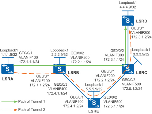
As shown in Figure 1, LSRA has two dynamic MPLS TE tunnels to LSRD: Tunnel1 and Tunnel2. The affinity attribute and mask need to be used according to the administrative group attribute so that Tunnel1 on LSRA uses the physical link LSRA -> LSRB -> LSRC -> LSRD and Tunnel2 uses the physical link LSRA -> LSRB -> LSRE -> LSRC -> LSRD.

In this scenario, to avoid loops, ensure that all connected interfaces have STP disabled and connected interfaces are removed from VLAN 1. If STP is enabled and VLANIF interfaces of switches are used to construct a Layer 3 ring network, an interface on the network will be blocked. As a result, Layer 3 services on the network cannot run normally.
Configuration Roadmap
The configuration roadmap is as follows:
Assign an IP address to each interface and configure OSPF to ensure that there are reachable routes between LSRs.
Configure an ID for each LSR and globally enable MPLS TE, RSVP-TE, CSPF on each node and interface, and enable OSPF TE.
Configure the administrative group attribute of the outbound interface of the tunnel on each LSR.
On the ingress node of the primary tunnel, create a tunnel interface, and specify the IP address, tunneling protocol, destination IP address, tunnel ID, and dynamic signaling protocol RSVP-TE for the tunnel interface.
Determine and configure the affinity attribute and mask for each tunnel according to the administrative group attribute and networking requirements.
Procedure
- Assign an IP address to each interface and configure OSPF.
# Configure LSRA. Configure IP addresses for interfaces of LSRB, LSRC, LSRD, and LSRE according to Figure 1. The configurations of LSRB, LSRC, LSRD, and LSRE are similar to the configuration of LSRA, and are not mentioned here.
<HUAWEI> system-view
[HUAWEI] sysname LSRA
[LSRA] vlan batch 100
[LSRA] interface vlanif 100
[LSRA-Vlanif100] ip address 172.1.1.1 255.255.255.0
[LSRA-Vlanif100] quit
[LSRA] interface gigabitethernet 0/0/1
[LSRA-GigabitEthernet0/0/1] port link-type trunk
[LSRA-GigabitEthernet0/0/1] port trunk allow-pass vlan 100
[LSRA-GigabitEthernet0/0/1] quit
[LSRA] interface loopback 1
[LSRA-LoopBack1] ip address 1.1.1.9 255.255.255.255
[LSRA-LoopBack1] quit
[LSRA] ospf 1
[LSRA-ospf-1] area 0
[LSRA-ospf-1-area-0.0.0.0] network 1.1.1.9 0.0.0.0
[LSRA-ospf-1-area-0.0.0.0] network 172.1.1.0 0.0.0.255
[LSRA-ospf-1-area-0.0.0.0] quit
[LSRA-ospf-1] quit
After the configurations are complete, run the display ip routing-table command on each LSR. You can see that the LSRs have learned the routes to Loopback1 interfaces of each other. The display on LSRA is used as an example.
[LSRA] display ip routing-table Route Flags: R - relay, D - download to fib, T - to vpn-instance ------------------------------------------------------------------------------ Routing Tables: Public Destinations : 13 Routes : 13 Destination/Mask Proto Pre Cost Flags NextHop Interface 1.1.1.9/32 Direct 0 0 D 127.0.0.1 LoopBack1 2.2.2.9/32 OSPF 10 1 D 172.1.1.2 Vlanif100 3.3.3.9/32 OSPF 10 2 D 172.1.1.2 Vlanif100 4.4.4.9/32 OSPF 10 3 D 172.1.1.2 Vlanif100 5.5.5.9/32 OSPF 10 2 D 172.1.1.2 Vlanif100 127.0.0.0/8 Direct 0 0 D 127.0.0.1 InLoopBack0 127.0.0.1/32 Direct 0 0 D 127.0.0.1 InLoopBack0 172.1.1.0/24 Direct 0 0 D 172.1.1.1 Vlanif100 172.1.1.1/32 Direct 0 0 D 127.0.0.1 Vlanif100 172.2.1.0/24 OSPF 10 2 D 172.1.1.2 Vlanif100 172.3.1.0/24 OSPF 10 3 D 172.1.1.2 Vlanif100 172.4.1.0/24 OSPF 10 2 D 172.1.1.2 Vlanif100 172.5.1.0/24 OSPF 10 3 D 172.1.1.2 Vlanif100 - Configure basic MPLS functions and enable MPLS TE, RSVP-TE,
and CSPF.
# Configure LSRA. The configurations of LSRB, LSRC, LSRD, and LSRE are similar to the configuration of LSRA, and are not mentioned here. CSPF only needs to be configured on the ingress node of the primary tunnel.
[LSRA] mpls lsr-id 1.1.1.9
[LSRA] mpls
[LSRA-mpls] mpls te
[LSRA-mpls] mpls rsvp-te
[LSRA-mpls] mpls te cspf
[LSRA-mpls] quit
[LSRA] interface vlanif 100
[LSRA-Vlanif100] mpls
[LSRA-Vlanif100] mpls te
[LSRA-Vlanif100] mpls rsvp-te
[LSRA-Vlanif100] quit
- Configure OSPF TE.
# Configure LSRA. The configurations of LSRB, LSRC, LSRD, and LSRE are similar to the configuration of LSRA, and are not mentioned here.
[LSRA] ospf
[LSRA-ospf-1] opaque-capability enable
[LSRA-ospf-1] area 0
[LSRA-ospf-1-area-0.0.0.0] mpls-te enable
[LSRA-ospf-1-area-0.0.0.0] quit
[LSRA-ospf-1] quit
- Set MPLS TE attributes of the outbound interface of each
node.
# Configure the administrative group attribute on LSRA.
[LSRA] interface vlanif 100
[LSRA-Vlanif100] mpls te link administrative group 10001
[LSRA-Vlanif100] quit
# Configure the administrative group attribute on LSRB.
[LSRB] interface vlanif 200
[LSRB-Vlanif200] mpls te link administrative group 10101
[LSRB-Vlanif200] quit
[LSRB] interface vlanif 400
[LSRB-Vlanif400] mpls te link administrative group 10011
[LSRB-Vlanif400] quit
# Configure the administrative group attribute on LSRC.
[LSRC] interface vlanif 300
[LSRC-Vlanif300] mpls te link administrative group 10001
[LSRC-Vlanif300] quit
# Configure the administrative group attribute on LSRE.
[LSRE] interface vlanif 500
[LSRE-Vlanif500] mpls te link administrative group 10011
[LSRE-Vlanif500] quit
After the configurations are complete, check the TEDB including the Color field of each link. The Color field indicates the administrative group attribute. The display on LSRA is used as an example.
[LSRA] display mpls te cspf tedb node Router ID: 1.1.1.9 IGP Type: OSPF Process ID: 1 MPLS-TE Link Count: 1 Link[1]: OSPF Router ID: 1.1.1.9 Opaque LSA ID: 1.0.0.1 Interface IP Address: 172.1.1.1 DR Address: 172.1.1.1 IGP Area: 0 Link Type: Multi-access Link Status: Active IGP Metric: 1 TE Metric: 1 Color: 0x10001 ... - Create MPLS TE tunnels on the ingress node.
# Create Tunnel1 on LSRA.
[LSRA] interface tunnel 1
[LSRA-Tunnel1] ip address unnumbered interface loopback 1
[LSRA-Tunnel1] tunnel-protocol mpls te
[LSRA-Tunnel1] destination 4.4.4.9
[LSRA-Tunnel1] mpls te tunnel-id 100
[LSRA-Tunnel1] mpls te record-route label
[LSRA-Tunnel1] mpls te affinity property 10101 mask 11011
[LSRA-Tunnel1] mpls te commit
[LSRA-Tunnel1] quit
# Create Tunnel2 on LSRA.
[LSRA] interface tunnel 2
[LSRA-Tunnel2] ip address unnumbered interface loopback 1
[LSRA-Tunnel2] tunnel-protocol mpls te
[LSRA-Tunnel2] destination 4.4.4.9
[LSRA-Tunnel2] mpls te tunnel-id 101
[LSRA-Tunnel2] mpls te record-route label
[LSRA-Tunnel2] mpls te affinity property 10011 mask 11101
[LSRA-Tunnel2] mpls te commit
[LSRA-Tunnel2] quit
- Verify the configuration.
After the configurations are complete, run the display mpls te tunnel-interface command to view the tunnel status on LSRA. You can see that both Tunnel1 and Tunnel2 are Up.
[LSRA] display mpls te tunnel-interface
    ----------------------------------------------------------------
                               Tunnel1
    ----------------------------------------------------------------
    Tunnel State Desc   :  UP
    Active LSP          :  Primary LSP
    Session ID          :  100
    Ingress LSR ID      :  1.1.1.9          Egress LSR ID:  4.4.4.9
    Admin State         :  UP               Oper State   :  UP
    Primary LSP State      : UP
      Main LSP State       : READY               LSP ID  : 47

    ----------------------------------------------------------------
                               Tunnel2
    ----------------------------------------------------------------
    Tunnel State Desc   :  UP
    Active LSP          :  Primary LSP
    Session ID          :  101
    Ingress LSR ID      :  1.1.1.9          Egress LSR ID:  4.4.4.9
    Admin State         :  UP               Oper State   :  UP
    Primary LSP State      : UP
      Main LSP State       : READY               LSP ID  : 4
Run the display mpls te tunnel path command to view the path of the tunnel. You can see that the affinity attribute and mask of the tunnel match the administrative group attribute of each link.
[LSRA] display mpls te tunnel path
 Tunnel Interface Name : Tunnel1
 Lsp ID : 1.1.1.9 :100 :47
 Hop Information
  Hop 0   172.1.1.1
  Hop 1   172.1.1.2  Label 1065
  Hop 2   2.2.2.9  Label 1065
  Hop 3   172.2.1.1
  Hop 4   172.2.1.2  Label 1075
  Hop 5   3.3.3.9  Label 1075
  Hop 6   172.3.1.1
  Hop 7   172.3.1.2  Label 3
  Hop 8   4.4.4.9  Label 3

 Tunnel Interface Name : Tunnel2
 Lsp ID : 1.1.1.9 :101 :4
 Hop Information
  Hop 0   172.1.1.1
  Hop 1   172.1.1.2  Label 1067
  Hop 2   2.2.2.9  Label 1067
  Hop 3   172.4.1.1
  Hop 4   172.4.1.2  Label 1040
  Hop 5   5.5.5.9  Label 1040
  Hop 6   172.5.1.1
  Hop 7   172.5.1.2  Label 1077
  Hop 8   3.3.3.9  Label 1077
  Hop 9   172.3.1.1
  Hop 10   172.3.1.2  Label 3
  Hop 11   4.4.4.9  Label 3
Configuration Files
LSRA configuration file
#
sysname LSRA
#
vlan batch 100
#
mpls lsr-id 1.1.1.9
mpls
 mpls te
 mpls rsvp-te
 mpls te cspf
#
interface Vlanif100
 ip address 172.1.1.1 255.255.255.0
 mpls
 mpls te
 mpls te link administrative group 10001
 mpls rsvp-te
#
interface GigabitEthernet0/0/1
 port link-type trunk
 port trunk allow-pass vlan 100
#
interface LoopBack1
 ip address 1.1.1.9 255.255.255.255
#
interface Tunnel1
 ip address unnumbered interface LoopBack1
 tunnel-protocol mpls te
 destination 4.4.4.9
 mpls te tunnel-id 100
 mpls te record-route label
 mpls te affinity property 10101 mask 11011
 mpls te commit
#
interface Tunnel2
 ip address unnumbered interface LoopBack1
 tunnel-protocol mpls te
 destination 4.4.4.9
 mpls te tunnel-id 101
 mpls te record-route label
 mpls te affinity property 10011 mask 11101
 mpls te commit
#
ospf 1
 opaque-capability enable
 area 0.0.0.0
  network 1.1.1.9 0.0.0.0
  network 172.1.1.0 0.0.0.255
  mpls-te enable
#
return
LSRB configuration file
#
sysname LSRB
#
vlan batch 100 200 400
#
mpls lsr-id 2.2.2.9
mpls
 mpls te
 mpls rsvp-te
#
interface Vlanif100
 ip address 172.1.1.2 255.255.255.0
 mpls
 mpls te
 mpls rsvp-te
#
interface Vlanif200
 ip address 172.2.1.1 255.255.255.0
 mpls
 mpls te
 mpls te link administrative group 10101
 mpls rsvp-te
#
interface Vlanif400
 ip address 172.4.1.1 255.255.255.0
 mpls
 mpls te
 mpls te link administrative group 10011
 mpls rsvp-te
#
interface GigabitEthernet0/0/1
 port link-type trunk
 port trunk allow-pass vlan 100
#
interface GigabitEthernet0/0/2
 port link-type trunk
 port trunk allow-pass vlan 200
#
interface GigabitEthernet0/0/3
 port link-type trunk
 port trunk allow-pass vlan 400
#
interface LoopBack1
 ip address 2.2.2.9 255.255.255.255
#
ospf 1
 opaque-capability enable
 area 0.0.0.0
  network 2.2.2.9 0.0.0.0
  network 172.1.1.0 0.0.0.255
  network 172.2.1.0 0.0.0.255
  network 172.4.1.0 0.0.0.255
  mpls-te enable
#
return
LSRC configuration file
#
sysname LSRC
#
vlan batch 200 300 500
#
mpls lsr-id 3.3.3.9
mpls
 mpls te
 mpls rsvp-te
#
interface Vlanif200
 ip address 172.2.1.2 255.255.255.0
 mpls
 mpls te
 mpls rsvp-te
#
interface Vlanif300
 ip address 172.3.1.1 255.255.255.0
 mpls
 mpls te
 mpls te link administrative group 10001
 mpls rsvp-te
#
interface Vlanif500
 ip address 172.5.1.2 255.255.255.0
 mpls
 mpls te
 mpls rsvp-te
#
interface GigabitEthernet0/0/1
 port link-type trunk
 port trunk allow-pass vlan 200
#
interface GigabitEthernet0/0/2
 port link-type trunk
 port trunk allow-pass vlan 300
#
interface GigabitEthernet0/0/3
 port link-type trunk
 port trunk allow-pass vlan 500
#
interface LoopBack1
 ip address 3.3.3.9 255.255.255.255
#
ospf 1
 opaque-capability enable
 area 0.0.0.0
  network 3.3.3.9 0.0.0.0
  network 172.2.1.0 0.0.0.255
  network 172.3.1.0 0.0.0.255
  network 172.5.1.0 0.0.0.255
  mpls-te enable
#
return
LSRD configuration file
#
sysname LSRD
#
vlan batch 300
#
mpls lsr-id 4.4.4.9
mpls
 mpls te
 mpls rsvp-te
#
interface Vlanif300
 ip address 172.3.1.2 255.255.255.0
 mpls
 mpls te
 mpls rsvp-te
#
interface GigabitEthernet0/0/1
 port link-type trunk
 port trunk allow-pass vlan 300
#
interface LoopBack1
 ip address 4.4.4.9 255.255.255.255
#
ospf 1
 opaque-capability enable
 area 0.0.0.0
  network 4.4.4.9 0.0.0.0
  network 172.3.1.0 0.0.0.255
  mpls-te enable
#
return
LSRE configuration file
#
sysname LSRE
#
vlan batch 400 500
#
mpls lsr-id 5.5.5.9
mpls
 mpls te
 mpls rsvp-te
#
interface Vlanif400
 ip address 172.4.1.2 255.255.255.0
 mpls
 mpls te
 mpls rsvp-te
#
interface Vlanif500
 ip address 172.5.1.1 255.255.255.0
 mpls
 mpls te
 mpls te link administrative group 10011
 mpls rsvp-te
#
interface GigabitEthernet0/0/1
 port link-type trunk
 port trunk allow-pass vlan 400
#
interface GigabitEthernet0/0/2
 port link-type trunk
 port trunk allow-pass vlan 500
#
interface LoopBack1
 ip address 5.5.5.9 255.255.255.255
#
ospf 1
 opaque-capability enable
 area 0.0.0.0
  network 5.5.5.9 0.0.0.0
  network 172.4.1.0 0.0.0.255
  network 172.5.1.0 0.0.0.255
  mpls-te enable
#
return