Example for Configuring Forwarding Adjacency to Direct Traffic to an MPLS TE Tunnel
Networking Requirements
An MPLS TE tunnel does not automatically direct traffic. To direct traffic to an MPLS TE tunnel, configure forwarding adjacency. Forwarding adjacency enables a device to use a TE tunnel as a logical link for IGP route calculation. Unlike IGP shortcut, forwarding adjacency advertises a TE tunnel to its peers as an IGP route. You can set a proper metric for an MPLS TE tunnel to ensure that the route passing through the MPLS TE tunnel is preferred, allowing traffic to be directed to the MPLS TE tunnel.
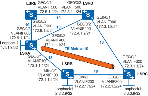
As shown in Figure 1, devices use OSPF to communicate with each other. An MPLS TE tunnel is established from LSRA and LSRC. The MPLS TE tunnel passes through LSRB. The number marked on each link indicates the link cost. If LSRA and LSRE have traffic destined for LSRC, traffic from the two LSRs is forwarded by GE0/0/1 on LSRD based on the OSPF route selection result. If LSRA requires 10 Mbit/s bandwidth to send traffic to LSRC, and LSRE requires 100 Mbit/s bandwidth to send traffic to LSRC, but the link between LSRC and LSRD has only 100 Mbit/s of bandwidth, the link is congested. Congestion on the link causes traffic transmission delay or packet loss.
To resolve this problem, configure forwarding adjacency on the MPLS TE tunnel interface of LSRA. Then all traffic from LSRA to LSRC is forwarded over the MPLS TE tunnel, whereas only some of traffic from LSRE to LSRC is forwarded over the MPLS TE tunnel. The rest of traffic is forwarded by LSRD. Therefore, traffic congestion is prevented over the link between LSRC and LSRD.

After you configure forwarding adjacency, LSRA advertises the MPLS TE tunnel to its peer as an OSPF route. Because OSPF requires bidirectional link detection, the MPLS TE tunnel from LSRC to LSRA must be established and forwarding adjacency must be configured on the tunnel interface.
In this scenario, to avoid loops, ensure that all connected interfaces have STP disabled and connected interfaces are removed from VLAN 1. If STP is enabled and VLANIF interfaces of switches are used to construct a Layer 3 ring network, an interface on the network will be blocked. As a result, Layer 3 services on the network cannot run normally.
Configuration Roadmap
The configuration roadmap is as follows:
Assign an IP address to each interface, configure OSPF to ensure that there are reachable routes between LSRs, and configure the OSPF cost.
On LSRA, create an MPLS TE tunnel over the path LSRA -> LSRB -> LSRC. On LSRC, create an MPLS TE tunnel over the path LSRC -> LSRB -> LSRA. This example uses RSVP-TE to establish a dynamic MPLS TE tunnel. Configure an ID for each LSR, enable MPLS TE, RSVP-TE, and CSPF on each node and interface, and enable OSPF TE. On the ingress node of the primary tunnel, create a tunnel interface, and specify the IP address, tunneling protocol, destination IP address, tunnel ID, and dynamic signaling protocol RSVP-TE for the tunnel interface.
Enable forwarding adjacency on the TE tunnel interfaces of LSRA and LSRC, and configure the IGP metric for the TE tunnels.
Procedure
- Assign an IP address to each interface, configure OSPF,
and set the OSPF cost.
# Configure LSRA. Configure IP addresses for interfaces of LSRB, LSRC, LSRD, and LSRE according to Figure 1. The configurations on LSRB, LSRC, LSRD, and LSRE are similar to the configuration of LSRA, and are not mentioned here.
<HUAWEI> system-view
[HUAWEI] sysname LSRA
[LSRA] vlan batch 100 400 600
[LSRA] interface vlanif 100
[LSRA-Vlanif100] ip address 172.1.1.1 255.255.255.0
[LSRA-Vlanif100] ospf cost 15
[LSRA-Vlanif100] quit
[LSRA] interface vlanif 400
[LSRA-Vlanif400] ip address 172.4.1.1 255.255.255.0
[LSRA-Vlanif400] ospf cost 10
[LSRA-Vlanif400] quit
[LSRA] interface vlanif 600
[LSRA-Vlanif600] ip address 172.6.1.1 255.255.255.0
[LSRA-Vlanif600] ospf cost 10
[LSRA-Vlanif600] quit
[LSRA] interface gigabitethernet 0/0/1
[LSRA-GigabitEthernet0/0/1] port link-type trunk
[LSRA-GigabitEthernet0/0/1] port trunk allow-pass vlan 100
[LSRA-GigabitEthernet0/0/1] quit
[LSRA] interface gigabitethernet 0/0/2
[LSRA-GigabitEthernet0/0/2] port link-type trunk
[LSRA-GigabitEthernet0/0/2] port trunk allow-pass vlan 400
[LSRA-GigabitEthernet0/0/2] quit
[LSRA] interface gigabitethernet 0/0/3
[LSRA-GigabitEthernet0/0/3] port link-type trunk
[LSRA-GigabitEthernet0/0/3] port trunk allow-pass vlan 600
[LSRA-GigabitEthernet0/0/3] quit
[LSRA] interface loopback 1
[LSRA-LoopBack1] ip address 1.1.1.9 255.255.255.255
[LSRA-LoopBack1] quit
[LSRA] ospf 1
[LSRA-ospf-1] area 0
[LSRA-ospf-1-area-0.0.0.0] network 1.1.1.9 0.0.0.0
[LSRA-ospf-1-area-0.0.0.0] network 172.1.1.0 0.0.0.255
[LSRA-ospf-1-area-0.0.0.0] network 172.4.1.0 0.0.0.255
[LSRA-ospf-1-area-0.0.0.0] network 172.6.1.0 0.0.0.255
[LSRA-ospf-1-area-0.0.0.0] quit
[LSRA-ospf-1] quit
After the configurations are complete, run the display ip routing-table command on LSRA, LSRB, and LSRC. You can see that PE1 and PE2 have learned the routes to Loopback1 interfaces of each other.
- Configure basic MPLS functions and enable MPLS TE, RSVP-TE,
and CSPF.
To create TE tunnels on LSRA and LSRC, perform the following configurations on LSRA, LSRB, and LSRC.
# Configure LSRA. The configurations on LSRB and LSRC are similar to the configuration of LSRA, and are not mentioned here. CSPF only needs to be configured on the ingress node of the primary tunnel.
[LSRA] mpls lsr-id 1.1.1.9
[LSRA] mpls
[LSRA-mpls] mpls te
[LSRA-mpls] mpls rsvp-te
[LSRA-mpls] mpls te cspf
[LSRA-mpls] quit
[LSRA] interface vlanif 100
[LSRA-Vlanif100] mpls
[LSRA-Vlanif100] mpls te
[LSRA-Vlanif100] mpls rsvp-te
[LSRA-Vlanif100] quit
- Configure OSPF TE.
To create TE tunnels on LSRA and LSRC, perform the following configurations on LSRA, LSRB, and LSRC.
# Configure LSRA. The configurations on LSRB and LSRC are similar to the configuration of LSRA, and are not mentioned here.
[LSRA] ospf
[LSRA-ospf-1] opaque-capability enable
[LSRA-ospf-1] area 0
[LSRA-ospf-1-area-0.0.0.0] mpls-te enable
[LSRA-ospf-1-area-0.0.0.0] quit
[LSRA-ospf-1] quit
- Create an MPLS TE tunnel.
Create MPLS TE tunnel interfaces on LSRA and LSRC, and configure explicit paths.
# Configure LSRA.
[LSRA] explicit-path pri-path
[LSRA-explicit-path-pri-path] next hop 172.1.1.2
[LSRA-explicit-path-pri-path] next hop 172.2.1.2
[LSRA-explicit-path-pri-path] next hop 3.3.3.9
[LSRA-explicit-path-pri-path] quit
[LSRA] interface tunnel 1
[LSRA-Tunnel1] ip address unnumbered interface loopback 1
[LSRA-Tunnel1] tunnel-protocol mpls te
[LSRA-Tunnel1] destination 3.3.3.9
[LSRA-Tunnel1] mpls te tunnel-id 100
[LSRA-Tunnel1] mpls te path explicit-path pri-path
[LSRA-Tunnel1] mpls te commit
[LSRA-Tunnel1] quit
# Configure LSRC.
[LSRC] explicit-path pri-path
[LSRC-explicit-path-pri-path] next hop 172.2.1.1
[LSRC-explicit-path-pri-path] next hop 172.1.1.1
[LSRC-explicit-path-pri-path] next hop 1.1.1.9
[LSRC-explicit-path-pri-path] quit
[LSRC] interface tunnel 1
[LSRC-Tunnel1] ip address unnumbered interface loopback 1
[LSRC-Tunnel1] tunnel-protocol mpls te
[LSRC-Tunnel1] destination 1.1.1.9
[LSRC-Tunnel1] mpls te tunnel-id 101
[LSRC-Tunnel1] mpls te path explicit-path pri-path
[LSRC-Tunnel1] mpls te commit
[LSRC-Tunnel1] quit
- Configure forwarding adjacency.
Enable forwarding adjacency on the TE tunnel interface of LSRA and set the IGP metric to 10 for the TE tunnel.
# Configure LSRA.
[LSRA] interface tunnel 1
[LSRA-Tunnel1] mpls te igp advertise
[LSRA-Tunnel1] mpls te igp metric absolute 10
[LSRA-Tunnel1] mpls te commit
[LSRA-Tunnel1] quit
[LSRA] ospf 1
[LSRA-ospf-1] enable traffic-adjustment advertise
[LSRA-ospf-1] quit
# Configure LSRC.
[LSRC] interface tunnel 1
[LSRC-Tunnel1] mpls te igp advertise
[LSRC-Tunnel1] mpls te igp metric absolute 10
[LSRC-Tunnel1] mpls te commit
[LSRC-Tunnel1] quit
[LSRC] ospf 1
[LSRC-ospf-1] enable traffic-adjustment advertise
[LSRC-ospf-1] quit
- Verify the configuration.
After the configurations are complete, run the display ip routing-table 3.3.3.9 command on LSRA. You can see that the next hop address of the route destined for LSRC (3.3.3.9) is 1.1.1.9 and the outbound interface of this route is Tunnel1. The traffic destined for LSRC has been directed to the MPLS TE tunnel.
[LSRA] display ip routing-table 3.3.3.9
Route Flags: R - relay, D - download to fib, T - to vpn-instance
------------------------------------------------------------------------------
Routing Table : Public
Summary Count : 1
Destination/Mask    Proto   Pre  Cost      Flags NextHop         Interface

        3.3.3.9/32  OSPF    10   10          D   1.1.1.9       Tunnel1
Run the display ip routing-table 3.3.3.9 command on LSRE. You can see that there are two equal-cost routes to LSRC (3.3.3.9). Some traffic destined for LSRC is forwarded by LSRD and some traffic is sent to the LSRA and forwarded over the MPLS TE tunnel.
[LSRE] display ip routing-table 3.3.3.9
Route Flags: R - relay, D - download to fib, T - to vpn-instance
------------------------------------------------------------------------------
Routing Table : Public
Summary Count : 2
Destination/Mask    Proto   Pre  Cost      Flags NextHop         Interface

        3.3.3.9/32  OSPF    10   20          D   172.5.1.1       Vlanif500
                    OSPF    10   20          D   172.6.1.1       Vlanif600
Configuration Files
LSRA configuration file
#
sysname LSRA
#
vlan batch 100 400 600
#
mpls lsr-id 1.1.1.9
mpls
 mpls te
 mpls rsvp-te
 mpls te cspf
#
explicit-path pri-path
 next hop 172.1.1.2
 next hop 172.2.1.2
 next hop 3.3.3.9
#
interface Vlanif100
 ip address 172.1.1.1 255.255.255.0
 ospf cost 15
 mpls
 mpls te
 mpls rsvp-te
#
interface Vlanif400
 ip address 172.4.1.1 255.255.255.0
 ospf cost 10
#
interface Vlanif600
 ip address 172.6.1.1 255.255.255.0
 ospf cost 10
#
interface GigabitEthernet0/0/1
 port link-type trunk
 port trunk allow-pass vlan 100
#
interface GigabitEthernet0/0/2
 port link-type trunk
 port trunk allow-pass vlan 400
#
interface GigabitEthernet0/0/3
 port link-type trunk
 port trunk allow-pass vlan 600
#
interface LoopBack1
 ip address 1.1.1.9 255.255.255.255
#
interface Tunnel1
 ip address unnumbered interface LoopBack1
 tunnel-protocol mpls te
 destination 3.3.3.9
 mpls te tunnel-id 100
 mpls te path explicit-path pri-path
 mpls te igp advertise
 mpls te igp metric absolute 10
 mpls te commit
#
ospf 1
 opaque-capability enable
 enable traffic-adjustment advertise
 area 0.0.0.0
  network 1.1.1.9 0.0.0.0
  network 172.1.1.0 0.0.0.255
  network 172.4.1.0 0.0.0.255
  network 172.6.1.0 0.0.0.255
  mpls-te enable
#
return
LSRB configuration file
#
sysname LSRB
#
vlan batch 100 200
#
mpls lsr-id 2.2.2.9
mpls
 mpls te
 mpls rsvp-te
#
interface Vlanif100
 ip address 172.1.1.2 255.255.255.0
 ospf cost 15
 mpls
 mpls te
 mpls rsvp-te
#
interface Vlanif200
 ip address 172.2.1.1 255.255.255.0
 ospf cost 10
 mpls
 mpls te
 mpls rsvp-te
#
interface GigabitEthernet0/0/1
 port link-type trunk
 port trunk allow-pass vlan 100
#
interface GigabitEthernet0/0/2
 port link-type trunk
 port trunk allow-pass vlan 200
#
interface LoopBack1
 ip address 2.2.2.9 255.255.255.255
#
ospf 1
 opaque-capability enable
 area 0.0.0.0
  network 2.2.2.9 0.0.0.0
  network 172.1.1.0 0.0.0.255
  network 172.2.1.0 0.0.0.255
  mpls-te enable
#
return
LSRC configuration file
#
sysname LSRC
#
vlan batch 200 300
#
mpls lsr-id 3.3.3.9
mpls
 mpls te
 mpls rsvp-te
 mpls te cspf
#
explicit-path pri-path
 next hop 172.2.1.1
 next hop 172.1.1.1
 next hop 1.1.1.9
#
interface Vlanif200
 ip address 172.2.1.2 255.255.255.0
 ospf cost 10
 mpls
 mpls te
 mpls rsvp-te
#
interface Vlanif300
 ip address 172.3.1.1 255.255.255.0
 ospf cost 10
#
interface GigabitEthernet0/0/1
 port link-type trunk
 port trunk allow-pass vlan 200
#
interface GigabitEthernet0/0/2
 port link-type trunk
 port trunk allow-pass vlan 300
#
interface LoopBack1
 ip address 3.3.3.9 255.255.255.255
#
interface Tunnel1
 ip address unnumbered interface LoopBack1
 tunnel-protocol mpls te
 destination 1.1.1.9
 mpls te tunnel-id 101
 mpls te path explicit-path pri-path
 mpls te igp advertise
 mpls te igp metric absolute 10
 mpls te commit
#
ospf 1
 opaque-capability enable
 enable traffic-adjustment advertise
 area 0.0.0.0
  network 3.3.3.9 0.0.0.0
  network 172.2.1.0 0.0.0.255
  network 172.3.1.0 0.0.0.255
  mpls-te enable
#
return
LSRD configuration file
#
sysname LSRD
#
vlan batch 300 400 500
#
interface Vlanif300
 ip address 172.3.1.2 255.255.255.0
 ospf cost 10
#
interface Vlanif400
 ip address 172.4.1.2 255.255.255.0
 ospf cost 10
#
interface Vlanif500
 ip address 172.5.1.1 255.255.255.0
 ospf cost 10
#
interface GigabitEthernet0/0/1
 port link-type trunk
 port trunk allow-pass vlan 300
#
interface GigabitEthernet0/0/2
 port link-type trunk
 port trunk allow-pass vlan 400
#
interface GigabitEthernet0/0/3
 port link-type trunk
 port trunk allow-pass vlan 500
#
ospf 1
 area 0.0.0.0
  network 172.3.1.0 0.0.0.255
  network 172.4.1.0 0.0.0.255
  network 172.5.1.0 0.0.0.255
#
return
LSRE configuration file
#
sysname LSRE
#
vlan batch 500 600
#
interface Vlanif500
 ip address 172.5.1.2 255.255.255.0
 ospf cost 10
#
interface Vlanif600
 ip address 172.6.1.2 255.255.255.0
 ospf cost 10
#
interface GigabitEthernet0/0/1
 port link-type trunk
 port trunk allow-pass vlan 500
#
interface GigabitEthernet0/0/2
 port link-type trunk
 port trunk allow-pass vlan 600
#
ospf 1
 area 0.0.0.0
  network 172.5.1.0 0.0.0.255
  network 172.6.1.0 0.0.0.255
#
return