Example for Configuring SRLG Based on Auto TE FRR
Networking Requirements
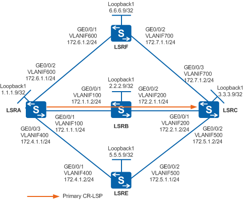
As shown in Figure 1, An MPLS TE tunnel is set up between LSRA and LSRC, with the path LSRA -> LSRB -> LSRC.
The link LSRA -> LSRB and link LSRA -> LSRE belong to the same SRLG (SRLG1 is used here).
To improve reliability, auto TE FRR needs to be configured and the links of the bypass CR-LSP and primary tunnel must be in different SRLGs. If no path is available, SRLG attributes can be ignored.

In this scenario, to avoid loops, ensure that all connected interfaces have STP disabled and connected interfaces are removed from VLAN 1. If STP is enabled and VLANIF interfaces of switches are used to construct a Layer 3 ring network, an interface on the network will be blocked. As a result, Layer 3 services on the network cannot run normally.
Configuration Roadmap
The configuration roadmap is as follows:
Assign an IP address to each interface and configure OSPF to ensure that there are reachable routes between LSRs.
Configure an ID for each LSR and globally enable MPLS, MPLS TE, RSVP-TE, CSPF on each node and interface, and enable OSPF TE.
On the ingress node of the primary tunnel, create a tunnel interface, and specify the IP address, tunneling protocol, destination IP address, tunnel ID, and dynamic signaling protocol RSVP-TE for the tunnel interface. The explicit path is LSRA -> LSRB -> LSRC.
Configure SRLG numbers for SRLG member interfaces.
Configure the SRLG path calculation mode on the ingress node of the primary tunnel.
Configure auto TE FRR on the ingress node of the primary tunnel to protect LSRB.
Procedure
- Assign an IP address to each interface and configure OSPF.
# Configure LSRA. Configure IP addresses for interfaces of LSRB, LSRC, LSRE, and LSRF according to Figure 1. The configurations of LSRB, LSRC, LSRE, and LSRF are similar to the configuration of LSRA, and are not mentioned here.
<HUAWEI> system-view
[HUAWEI] sysname LSRA
[LSRA] vlan batch 100 400 600
[LSRA] interface vlanif 100
[LSRA-Vlanif100] ip address 172.1.1.1 255.255.255.0
[LSRA-Vlanif100] quit
[LSRA] interface vlanif 400
[LSRA-Vlanif400] ip address 172.4.1.1 255.255.255.0
[LSRA-Vlanif400] quit
[LSRA] interface vlanif 600
[LSRA-Vlanif600] ip address 172.6.1.1 255.255.255.0
[LSRA-Vlanif600] quit
[LSRA] interface gigabitethernet 0/0/1
[LSRA-GigabitEthernet0/0/1] port link-type trunk
[LSRA-GigabitEthernet0/0/1] port trunk allow-pass vlan 100
[LSRA-GigabitEthernet0/0/1] quit
[LSRA] interface gigabitethernet 0/0/2
[LSRA-GigabitEthernet0/0/2] port link-type trunk
[LSRA-GigabitEthernet0/0/2] port trunk allow-pass vlan 600
[LSRA-GigabitEthernet0/0/2] quit
[LSRA] interface gigabitethernet 0/0/3
[LSRA-GigabitEthernet0/0/3] port link-type trunk
[LSRA-GigabitEthernet0/0/3] port trunk allow-pass vlan 400
[LSRA-GigabitEthernet0/0/3] quit
[LSRA] interface loopback 1
[LSRA-LoopBack1] ip address 1.1.1.9 255.255.255.255
[LSRA-LoopBack1] quit
[LSRA] ospf 1
[LSRA-ospf-1] area 0
[LSRA-ospf-1-area-0.0.0.0] network 1.1.1.9 0.0.0.0
[LSRA-ospf-1-area-0.0.0.0] network 172.1.1.0 0.0.0.255
[LSRA-ospf-1-area-0.0.0.0] network 172.4.1.0 0.0.0.255
[LSRA-ospf-1-area-0.0.0.0] network 172.6.1.0 0.0.0.255
[LSRA-ospf-1-area-0.0.0.0] quit
[LSRA-ospf-1] quit
After the configurations are complete, run the display ip routing-table command on each LSR. You can see that the LSRs learn the routes to Loopback1 of each other. The display on LSRA is used as an example.
[LSRA] display ip routing-table Route Flags: R - relay, D - download to fib, T - to vpn-instance ------------------------------------------------------------------------------ Routing Tables: Public Destinations : 16 Routes : 18 Destination/Mask Proto Pre Cost Flags NextHop Interface 1.1.1.9/32 Direct 0 0 D 127.0.0.1 LoopBack1 2.2.2.9/32 OSPF 10 1 D 172.1.1.2 Vlanif100 3.3.3.9/32 OSPF 10 2 D 172.1.1.2 Vlanif100 OSPF 10 2 D 172.4.1.2 Vlanif400 OSPF 10 2 D 172.6.1.2 Vlanif600 5.5.5.9/32 OSPF 10 1 D 172.4.1.2 Vlanif400 6.6.6.9/32 OSPF 10 1 D 172.6.1.2 Vlanif600 127.0.0.0/8 Direct 0 0 D 127.0.0.1 InLoopBack0 127.0.0.1/32 Direct 0 0 D 127.0.0.1 InLoopBack0 172.1.1.0/24 Direct 0 0 D 172.1.1.1 Vlanif100 172.1.1.1/32 Direct 0 0 D 127.0.0.1 Vlanif100 172.2.1.0/24 OSPF 10 2 D 172.1.1.2 Vlanif100 172.4.1.0/24 Direct 0 0 D 172.4.1.1 Vlanif400 172.4.1.1/32 Direct 0 0 D 127.0.0.1 Vlanif400 172.5.1.0/24 OSPF 10 2 D 172.4.1.2 Vlanif400 172.6.1.0/24 Direct 0 0 D 172.6.1.1 Vlanif600 172.6.1.1/32 Direct 0 0 D 127.0.0.1 Vlanif600 172.7.1.0/24 OSPF 10 2 D 172.6.1.2 Vlanif600 - Configure basic MPLS functions and enable MPLS TE, RSVP-TE,
and CSPF.
# Configure LSRA. The configurations of LSRB, LSRC, LSRE, and LSRF are similar to the configuration of LSRA, and are not mentioned here. CSPF only needs to be configured on the ingress node of the primary tunnel.
[LSRA] mpls lsr-id 1.1.1.9
[LSRA] mpls
[LSRA-mpls] mpls te
[LSRA-mpls] mpls rsvp-te
[LSRA-mpls] mpls te cspf
[LSRA-mpls] quit
[LSRA] interface vlanif 100
[LSRA-Vlanif100] mpls
[LSRA-Vlanif100] mpls te
[LSRA-Vlanif100] mpls rsvp-te
[LSRA-Vlanif100] quit
[LSRA] interface vlanif 400
[LSRA-Vlanif400] mpls
[LSRA-Vlanif400] mpls te
[LSRA-Vlanif400] mpls rsvp-te
[LSRA-Vlanif400] quit
[LSRA] interface vlanif 600
[LSRA-Vlanif600] mpls
[LSRA-Vlanif600] mpls te
[LSRA-Vlanif600] mpls rsvp-te
[LSRA-Vlanif600] quit
- Configure OSPF TE.
# Configure LSRA. The configurations of LSRB, LSRC, LSRE, and LSRF are similar to the configuration of LSRA, and are not mentioned here.
[LSRA] ospf
[LSRA-ospf-1] opaque-capability enable
[LSRA-ospf-1] area 0
[LSRA-ospf-1-area-0.0.0.0] mpls-te enable
[LSRA-ospf-1-area-0.0.0.0] quit
[LSRA-ospf-1] quit
- On LSRA, create an MPLS TE tunnel for the primary CR-LSP.
# Configure the explicit path of the primary CR-LSP.
[LSRA] explicit-path pri-path
[LSRA-explicit-path-pri-path] next hop 172.1.1.2
[LSRA-explicit-path-pri-path] next hop 172.2.1.2
[LSRA-explicit-path-pri-path] next hop 3.3.3.9
[LSRA-explicit-path-pri-path] quit
# Configure the MPLS TE tunnel interface of the primary CR-LSP.
[LSRA] interface tunnel 1
[LSRA-Tunnel1] ip address unnumbered interface loopBack 1
[LSRA-Tunnel1] tunnel-protocol mpls te
[LSRA-Tunnel1] destination 3.3.3.9
[LSRA-Tunnel1] mpls te tunnel-id 100
[LSRA-Tunnel1] mpls te path explicit-path pri-path
[LSRA-Tunnel1] mpls te commit
[LSRA-Tunnel1] quit
Run the display interface tunnel 1 command on LSRA. You can see that the tunnel status is Up.
[LSRA] display interface tunnel 1
Tunnel1 current state : UP
Line protocol current state : UP
Last line protocol up time : 2013-01-22 16:57:00
Description:
...
- Configure SRLG.
Add links LSRA -> LSRB and LSRA -> LSRE to SRLG1, and configure the SRLG path calculation mode on the ingress node LSRA of the primary tunnel.
# Configure LSRA.
[LSRA] interface vlanif 100
[LSRA-Vlanif100] mpls te srlg 1
[LSRA-Vlanif100] quit
[LSRA] interface vlanif 400
[LSRA-Vlanif400] mpls te srlg 1
[LSRA-Vlanif400] quit
# Configure the SRLG path calculation mode on LSRA.
[LSRA] mpls
[LSRA-mpls] mpls te srlg path-calculation preferred
[LSRA-mpls] quit
Run the display mpls te srlg all command to view SRLG information and the interfaces that belong to the SRLG. The display on LSRA is used as an example.
[LSRA] display mpls te srlg all
Total SRLG supported : 1024
Total SRLG configured : 2
SRLG    1:           Vlanif100             Vlanif400
Run the display mpls te link-administration srlg-information to view SRLGs to which the interfaces belong. The display on LSRA is used as an example.
[LSRA] display mpls te link-administration srlg-information

 SRLGs on Vlanif100 :
              1

 SRLGs on Vlanif400 :
              1
Run the display mpls te cspf tedb srlg command to view TEDB information of the specified SRLG.
[LSRA] display mpls te cspf tedb srlg 1
Interface-Address   IGP-Type            Area
172.1.1.1           OSPF                0
172.4.1.1           OSPF                0
- Configure auto TE FRR.
# Configure LSRA.
[LSRA] mpls
[LSRA-mpls] mpls te auto-frr
[LSRA-mpls] quit
[LSRA] interface tunnel 1
[LSRA-Tunnel1] mpls te fast-reroute
[LSRA-Tunnel1] mpls te commit
[LSRA-Tunnel1] quit
Run the display mpls te tunnel command on LSRA. You can see that the bypass CR-LSP has been established.
[LSRA] display mpls te tunnel
------------------------------------------------------------------------------
Ingress LsrId    Destination      LSPID   In/Out Label     R  Tunnel-name
------------------------------------------------------------------------------
1.1.1.9          3.3.3.9          1       --/1024          I  Tunnel1
1.1.1.9          3.3.3.9          4       --/1025          I  Tunnel2048
Run the display mpls te tunnel path Tunnel1 command on LSRA. You can see that local protection is enabled on the outbound interface (172.1.1.1) of the primary tunnel on LSRA.
[LSRA] display mpls te tunnel path Tunnel1
 Tunnel Interface Name : Tunnel1
 Lsp ID : 1.1.1.9 :100 :1
 Hop Information
  Hop 0   172.1.1.1 Local-Protection available | node
  Hop 1   172.1.1.2  Label 1024
  Hop 2   2.2.2.9  Label 1024
  Hop 3   172.2.1.1
  Hop 4   172.2.1.2  Label 3
  Hop 5   3.3.3.9  Label 3
- Verify the configuration.
After the configurations are complete, run the display mpls te tunnel name Tunnel1 verbose command on LSRA. You can see that the primary tunnel is bound to a bypass CR-LSP (Tunnel2048) and the FRR next hop is 172.7.1.2.
[LSRA] display mpls te tunnel name Tunnel1 verbose
    No                      :  1
    Tunnel-Name             :  Tunnel1
    Tunnel Interface Name   :  Tunnel1
    TunnelIndex             :  0           LSP Index         :  2048
    Session ID              :  100         LSP ID            :  1
    LSR Role                :  Ingress     LSP Type          :  Primary
    Ingress LSR ID          :  1.1.1.9
    Egress LSR ID           :  3.3.3.9
    In-Interface            :  -
    Out-Interface           :  Vlanif100
    Sign-Protocol           :  RSVP TE     Resv Style        :  SE
    IncludeAnyAff           :  0x0         ExcludeAnyAff     :  0x0
    IncludeAllAff           :  0x0
    LspConstraint           :  -
    ER-Hop Table Index      :  0           AR-Hop Table Index:  1
    C-Hop Table Index       :  1
    PrevTunnelIndexInSession:  -           NextTunnelIndexInSession:  -
    PSB Handle              :  8198
    Created Time            :  2013-09-16 15:20:42+00:00
    RSVP LSP Type           :  -
    --------------------------------
              DS-TE Information
    --------------------------------
    Bandwidth Reserved Flag :  Unreserved
    CT0 Bandwidth(Kbit/sec) :  0           CT1 Bandwidth(Kbit/sec):  0
    CT2 Bandwidth(Kbit/sec) :  0           CT3 Bandwidth(Kbit/sec):  0
    CT4 Bandwidth(Kbit/sec) :  0           CT5 Bandwidth(Kbit/sec):  0
    CT6 Bandwidth(Kbit/sec) :  0           CT7 Bandwidth(Kbit/sec):  0
    Setup-Priority          :  7           Hold-Priority     :  7
    --------------------------------
                FRR Information
    --------------------------------
    Primary LSP Info
    TE Attribute Flag       :  0x63        Protected Flag    :  0x2
    Bypass In Use           :  Not Used
    Bypass Tunnel Id        :  11
    BypassTunnel            :  Tunnel Index[Tunnel2048], InnerLabel[1024]
    Bypass LSP ID           :  4           FrrNextHop        :  172.7.1.2
    ReferAutoBypassHandle   :  -
    FrrPrevTunnelTableIndex :  -           FrrNextTunnelTableIndex:  -
    Bypass Attribute(Not configured)
    Setup Priority          :  -           Hold Priority     :  -
    HopLimit                :  -           Bandwidth         :  -
    IncludeAnyGroup         :  -           ExcludeAnyGroup   :  -
    IncludeAllGroup         :  -
    Bypass Unbound Bandwidth Info(Kbit/sec)
    CT0 Unbound Bandwidth   :  -         CT1 Unbound Bandwidth:  -
    CT2 Unbound Bandwidth   :  -         CT3 Unbound Bandwidth:  -
    CT4 Unbound Bandwidth   :  -         CT5 Unbound Bandwidth:  -
    CT6 Unbound Bandwidth   :  -         CT7 Unbound Bandwidth:  -
    --------------------------------
               BFD Information
    --------------------------------
    NextSessionTunnelIndex  :  -           PrevSessionTunnelIndex:  -
    NextLspId               :  -           PrevLspId         :  -
# Run the display mpls te tunnel path Tunnel2048 command on LSRA to check the path of the bypass CR-LSP. You can see that the path of the bypass CR-LSP is LSRA -> LSRF -> LSRC.
[LSRA] display mpls te tunnel path Tunnel2048
 Tunnel Interface Name : Tunnel2048
 Lsp ID : 1.1.1.9 :1025 :4
 Hop Information
  Hop 0   172.6.1.1
  Hop 1   172.6.1.2  Label 1025
  Hop 2   6.6.6.9  Label 1025
  Hop 3   172.7.1.1
  Hop 4   172.7.1.2  Label 3
  Hop 5   3.3.3.9  Label 3
# Run the shutdown command on GE0/0/2 of LSRA.
[LSRA] interface gigabitethernet 0/0/2
[LSRA-GigabitEthernet0/0/2] shutdown
[LSRA-GigabitEthernet0/0/2] quit
# Run the display mpls te tunnel name Tunnel1 verbose command on LSRA. You can see that the primary tunnel is bound to Tunnel2049 and the FRR next hop is 172.5.1.2.
[LSRA] display mpls te tunnel name Tunnel1 verbose
    No                      :  1
    Tunnel-Name             :  Tunnel1
    Tunnel Interface Name   :  Tunnel1
    TunnelIndex             :  0           LSP Index         :  2048
    Session ID              :  100         LSP ID            :  1
    LSR Role                :  Ingress     LSP Type          :  Primary
    Ingress LSR ID          :  1.1.1.9
    Egress LSR ID           :  3.3.3.9
    In-Interface            :  -
    Out-Interface           :  Vlanif100
    Sign-Protocol           :  RSVP TE     Resv Style        :  SE
    IncludeAnyAff           :  0x0         ExcludeAnyAff     :  0x0
    IncludeAllAff           :  0x0
    LspConstraint           :  -
    ER-Hop Table Index      :  0           AR-Hop Table Index:  1
    C-Hop Table Index       :  1
    PrevTunnelIndexInSession:  -           NextTunnelIndexInSession:  -
    PSB Handle              :  8198
    Created Time            :  2013-09-16 15:20:42+00:00
    RSVP LSP Type           :  -
    --------------------------------
              DS-TE Information
    --------------------------------
    Bandwidth Reserved Flag :  Unreserved
    CT0 Bandwidth(Kbit/sec) :  0           CT1 Bandwidth(Kbit/sec):  0
    CT2 Bandwidth(Kbit/sec) :  0           CT3 Bandwidth(Kbit/sec):  0
    CT4 Bandwidth(Kbit/sec) :  0           CT5 Bandwidth(Kbit/sec):  0
    CT6 Bandwidth(Kbit/sec) :  0           CT7 Bandwidth(Kbit/sec):  0
    Setup-Priority          :  7           Hold-Priority     :  7
    --------------------------------
                FRR Information
    --------------------------------
    Primary LSP Info
    TE Attribute Flag       :  0x63        Protected Flag    :  0x2
    Bypass In Use           :  Not Used
    Bypass Tunnel Id        :  11
    BypassTunnel            :  Tunnel Index[Tunnel2049], InnerLabel[1024]
    Bypass LSP ID           :  4           FrrNextHop        :  172.5.1.2
    ReferAutoBypassHandle   :  -
    FrrPrevTunnelTableIndex :  -           FrrNextTunnelTableIndex:  -
    Bypass Attribute(Not configured)
    Setup Priority          :  -           Hold Priority     :  -
    HopLimit                :  -           Bandwidth         :  -
    IncludeAnyGroup         :  -           ExcludeAnyGroup   :  -
    IncludeAllGroup         :  -
    Bypass Unbound Bandwidth Info(Kbit/sec)
    CT0 Unbound Bandwidth   :  -         CT1 Unbound Bandwidth:  -
    CT2 Unbound Bandwidth   :  -         CT3 Unbound Bandwidth:  -
    CT4 Unbound Bandwidth   :  -         CT5 Unbound Bandwidth:  -
    CT6 Unbound Bandwidth   :  -         CT7 Unbound Bandwidth:  -
    --------------------------------
               BFD Information
    --------------------------------
    NextSessionTunnelIndex  :  -           PrevSessionTunnelIndex:  -
    NextLspId               :  -           PrevLspId         :  -
# Run the display mpls te tunnel path Tunnel2049 command to check the path of the bypass CR-LSP.
[LSRA] display mpls te tunnel path Tunnel2049
 Tunnel Interface Name : Tunnel2049
 Lsp ID : 1.1.1.9 :1026 :4
 Hop Information
  Hop 0   172.4.1.1
  Hop 1   172.4.1.2  Label 1026
  Hop 2   5.5.5.9  Label 1026
  Hop 3   172.5.1.1
  Hop 4   172.5.1.2  Label 3
  Hop 5   3.3.3.9  Label 3
You can see that the path of the bypass CR-LSP is LSRA -> LSRE -> LSRC. This is because the SRLG path calculation mode is configured as preferred. CSPF tries to calculate the path of the bypass tunnel to avoid the links in the same SRLG as the protected interface(s). If calculation fails, CSPF does not take the SRLG as a constraint.
Configuration Files
LSRA configuration file
#
sysname LSRA
#
vlan batch 100 400 600
#
mpls lsr-id 1.1.1.9
mpls
 mpls te
 mpls te auto-frr
 mpls te srlg path-calculation preferred
 mpls rsvp-te
 mpls te cspf
#
explicit-path pri-path
 next hop 172.1.1.2
 next hop 172.2.1.2
 next hop 3.3.3.9
#
interface Vlanif100
 ip address 172.1.1.1 255.255.255.0
 mpls
 mpls te
 mpls te srlg 1
 mpls rsvp-te
#
interface Vlanif400
 ip address 172.4.1.1 255.255.255.0
 mpls
 mpls te
 mpls te srlg 1
 mpls rsvp-te
#
interface Vlanif600
 ip address 172.6.1.1 255.255.255.0
 mpls
 mpls te
 mpls rsvp-te
#
interface GigabitEthernet0/0/1
 port link-type trunk
 port trunk allow-pass vlan 100
#
interface GigabitEthernet0/0/2
 port link-type trunk
 port trunk allow-pass vlan 600
#
interface GigabitEthernet0/0/3
 port link-type trunk
 port trunk allow-pass vlan 400
#
interface LoopBack1
 ip address 1.1.1.9 255.255.255.255
#
interface Tunnel1
 ip address unnumbered interface LoopBack1
 tunnel-protocol mpls te
 destination 3.3.3.9
 mpls te tunnel-id 100
 mpls te record-route label
 mpls te path explicit-path pri-path
 mpls te fast-reroute
 mpls te commit
#
ospf 1
 opaque-capability enable
 area 0.0.0.0
  network 1.1.1.9 0.0.0.0
  network 172.1.1.0 0.0.0.255
  network 172.4.1.0 0.0.0.255
  network 172.6.1.0 0.0.0.255
  mpls-te enable
#
return
LSRB configuration file
#
sysname LSRB
#
vlan batch 100 200
#
mpls lsr-id 2.2.2.9
mpls
 mpls te
 mpls rsvp-te
#
interface Vlanif100
 ip address 172.1.1.2 255.255.255.0
 mpls
 mpls te
 mpls rsvp-te
#
interface Vlanif200
 ip address 172.2.1.1 255.255.255.0
 mpls
 mpls te
 mpls rsvp-te
#
interface GigabitEthernet0/0/1
 port link-type trunk
 port trunk allow-pass vlan 100
#
interface GigabitEthernet0/0/2
 port link-type trunk
 port trunk allow-pass vlan 200
#
interface LoopBack1
 ip address 2.2.2.9 255.255.255.255
#
ospf 1
 opaque-capability enable
 area 0.0.0.0
  network 2.2.2.9 0.0.0.0
  network 172.1.1.0 0.0.0.255
  network 172.2.1.0 0.0.0.255
  mpls-te enable
#
return
LSRC configuration file
#
sysname LSRC
#
vlan batch 200 500 700
#
mpls lsr-id 3.3.3.9
mpls
 mpls te
 mpls rsvp-te
#
interface Vlanif200
 ip address 172.2.1.2 255.255.255.0
 mpls
 mpls te
 mpls rsvp-te
#
interface Vlanif500
 ip address 172.5.1.2 255.255.255.0
 mpls
 mpls te
 mpls rsvp-te
#
interface Vlanif700
 ip address 172.7.1.2 255.255.255.0
 mpls
 mpls te
 mpls rsvp-te
#
interface GigabitEthernet0/0/1
 port link-type trunk
 port trunk allow-pass vlan 200
#
interface GigabitEthernet0/0/2
 port link-type trunk
 port trunk allow-pass vlan 500
#
interface GigabitEthernet0/0/3
 port link-type trunk
 port trunk allow-pass vlan 700
#
interface LoopBack1
 ip address 3.3.3.9 255.255.255.255
#
ospf 1
 opaque-capability enable
 area 0.0.0.0
  network 3.3.3.9 0.0.0.0
  network 172.2.1.0 0.0.0.255
  network 172.5.1.0 0.0.0.255
  network 172.7.1.0 0.0.0.255
  mpls-te enable
#
return
LSRE configuration file
#
sysname LSRE
#
vlan batch 400 500
#
mpls lsr-id 5.5.5.9
mpls
 mpls te
 mpls rsvp-te
#
interface Vlanif400
 ip address 172.4.1.2 255.255.255.0
 mpls
 mpls te
 mpls rsvp-te
#
interface Vlanif500
 ip address 172.5.1.1 255.255.255.0
 mpls
 mpls te
 mpls rsvp-te
#
interface GigabitEthernet0/0/1
 port link-type trunk
 port trunk allow-pass vlan 400
#
interface GigabitEthernet0/0/2
 port link-type trunk
 port trunk allow-pass vlan 500
#
interface LoopBack1
 ip address 5.5.5.9 255.255.255.255
#
ospf 1
 opaque-capability enable
 area 0.0.0.0
  network 5.5.5.9 0.0.0.0
  network 172.4.1.0 0.0.0.255
  network 172.5.1.0 0.0.0.255
  mpls-te enable
#
return
LSRF configuration file
#
sysname LSRF
#
vlan batch 600 700
#
mpls lsr-id 6.6.6.9
mpls
 mpls te
 mpls rsvp-te
#
interface Vlanif600
 ip address 172.6.1.2 255.255.255.0
 mpls
 mpls te
 mpls rsvp-te
#
interface Vlanif700
 ip address 172.7.1.1 255.255.255.0
 mpls
 mpls te
 mpls rsvp-te
#
interface GigabitEthernet0/0/1
 port link-type trunk
 port trunk allow-pass vlan 600
#
interface GigabitEthernet0/0/2
 port link-type trunk
 port trunk allow-pass vlan 700
#
interface LoopBack1
 ip address 6.6.6.9 255.255.255.255
#
ospf 1
 opaque-capability enable
 area 0.0.0.0
  network 6.6.6.9 0.0.0.0
  network 172.6.1.0 0.0.0.255
  network 172.7.1.0 0.0.0.255
  mpls-te enable
#
return