Example for Configuring Manual TE FRR
Networking Requirements
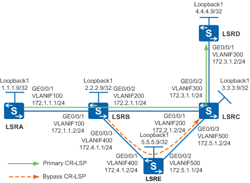
As shown in Figure 1, the primary CR-LSP is along the path LSRA -> LSRB -> LSRC -> LSRD, and the link between LSRB and LSRC needs to be protected by FRR.
A bypass CR-LSP is set up along the path LSRB -> LSRE -> LSRC. LSRB functions as the PLR and LSRC functions as the MP.
The primary and bypass MPLS TE tunnels need to be set up by using explicit paths. RSVP-TE is used as the signaling protocol.

In this scenario, to avoid loops, ensure that all connected interfaces have STP disabled and connected interfaces are removed from VLAN 1. If STP is enabled and VLANIF interfaces of switches are used to construct a Layer 3 ring network, an interface on the network will be blocked. As a result, Layer 3 services on the network cannot run normally.
Configuration Roadmap
The configuration roadmap is as follows:
Assign an IP address to each interface, enable IS-IS globally, configure the NET, and enable IS-IS on each interface including the loopback interface.
Configure an ID for each LSR and globally enable MPLS, MPLS TE, RSVP-TE, and CSPF on each node and interface. Enable IS-IS TE and change the cost type.
On the ingress node of the primary tunnel, create a tunnel interface, and specify the IP address, tunneling protocol, destination IP address, tunnel ID, and dynamic signaling protocol RSVP-TE for the tunnel interface.
Enable TE FRR on the interface of the primary tunnel on the ingress node.
Create a tunnel interface on the ingress node LSRB of the bypass tunnel of the protected link, set the IP address, tunnel protocol, destination IP address, tunnel ID, and RSVP-TE for the tunnel interface, and specify the interface of the protected link.
Procedure
- Assign IP addresses to interfaces.
# Configure LSRA. Configure IP addresses for interfaces of LSRB, LSRC, LSRD, and LSRE according to Figure 1. The configurations of LSRB, LSRC, LSRD, and LSRE are similar to the configuration of LSRA, and are not mentioned here.
<HUAWEI> system-view
[HUAWEI] sysname LSRA
[LSRA] vlan batch 100
[LSRA] interface vlanif 100
[LSRA-Vlanif100] ip address 172.1.1.1 255.255.255.0
[LSRA-Vlanif100] quit
[LSRA] interface gigabitethernet 0/0/1
[LSRA-GigabitEthernet0/0/1] port link-type trunk
[LSRA-GigabitEthernet0/0/1] port trunk allow-pass vlan 100
[LSRA-GigabitEthernet0/0/1] quit
[LSRA] interface loopback 1
[LSRA-LoopBack1] ip address 1.1.1.9 255.255.255.255
[LSRA-LoopBack1] quit
- Configure IS-IS to advertise routes.
# Configure LSRA. The configurations of LSRB, LSRC, LSRD, and LSRE are similar to the configuration of LSRA, and are not mentioned here.
[LSRA] isis 1
[LSRA-isis-1] network-entity 00.0005.0000.0000.0001.00
[LSRA-isis-1] is-level level-2
[LSRA-isis-1] quit
[LSRA] interface vlanif 100
[LSRA-Vlanif100] isis enable 1
[LSRA-Vlanif100] quit
[LSRA] interface loopback 1
[LSRA-LoopBack1] isis enable 1
[LSRA-LoopBack1] quit
After the configurations are complete, run the display ip routing-table command on each LSR. You can see that the LSRs learn the routes from each other. The display on LSRA is used as an example.
[LSRA] display ip routing-table Route Flags: R - relay, D - download to fib, T - to vpn-instance ------------------------------------------------------------------------------ Routing Tables: Public Destinations : 13 Routes : 13 Destination/Mask Proto Pre Cost Flags NextHop Interface 1.1.1.9/32 Direct 0 0 D 127.0.0.1 LoopBack1 2.2.2.9/32 ISIS-L2 15 10 D 172.1.1.2 Vlanif100 3.3.3.9/32 ISIS-L2 15 20 D 172.1.1.2 Vlanif100 4.4.4.9/32 ISIS-L2 15 30 D 172.1.1.2 Vlanif100 5.5.5.9/32 ISIS-L2 15 20 D 172.1.1.2 Vlanif100 127.0.0.0/8 Direct 0 0 D 127.0.0.1 InLoopBack0 127.0.0.1/32 Direct 0 0 D 127.0.0.1 InLoopBack0 172.1.1.0/24 Direct 0 0 D 172.1.1.1 Vlanif100 172.1.1.1/32 Direct 0 0 D 127.0.0.1 Vlanif100 172.2.1.0/24 ISIS-L2 15 20 D 172.1.1.2 Vlanif100 172.3.1.0/24 ISIS-L2 15 30 D 172.1.1.2 Vlanif100 172.4.1.0/24 ISIS-L2 15 20 D 172.1.1.2 Vlanif100 172.5.1.0/24 ISIS-L2 15 30 D 172.1.1.2 Vlanif100 - Configure basic MPLS functions and enable MPLS TE, CSPF,
RSVP-TE, and IS-IS TE.
# Configure LSRA. The configurations of LSRB, LSRC, LSRD, and LSRE are similar to the configuration of LSRA, and are not mentioned here. CSPF needs to be enabled only on the ingress node of the primary tunnel (LSRA) and the ingress node LSRB of the bypass tunnel (LSRB); CSPF does not need to be enabled on LSRC, LSRD, or LSRE.
[LSRA] mpls lsr-id 1.1.1.9
[LSRA] mpls
[LSRA-mpls] mpls te
[LSRA-mpls] mpls rsvp-te
[LSRA-mpls] mpls te cspf
[LSRA-mpls] quit
[LSRA] interface vlanif 100
[LSRA-Vlanif100] mpls
[LSRA-Vlanif100] mpls te
[LSRA-Vlanif100] mpls rsvp-te
[LSRA-Vlanif100] quit
[LSRA] isis
[LSRA-isis-1] cost-style wide
[LSRA-isis-1] traffic-eng level-2
[LSRA-isis-1] quit
- On LSRA, create an MPLS TE tunnel for the primary CR-LSP.
# Configure the explicit path of the primary CR-LSP.
[LSRA] explicit-path pri-path
[LSRA-explicit-path-pri-path] next hop 172.1.1.2
[LSRA-explicit-path-pri-path] next hop 172.2.1.2
[LSRA-explicit-path-pri-path] next hop 172.3.1.2
[LSRA-explicit-path-pri-path] next hop 4.4.4.9
[LSRA-explicit-path-pri-path] quit
# Configure the MPLS TE tunnel interface of the primary CR-LSP.
[LSRA] interface tunnel 1
[LSRA-Tunnel1] ip address unnumbered interface loopback 1
[LSRA-Tunnel1] tunnel-protocol mpls te
[LSRA-Tunnel1] destination 4.4.4.9
[LSRA-Tunnel1] mpls te tunnel-id 100
[LSRA-Tunnel1] mpls te path explicit-path pri-path
# Enable TE FRR.
[LSRA-Tunnel1] mpls te fast-reroute
[LSRA-Tunnel1] mpls te commit
[LSRA-Tunnel1] quit
After the configurations are complete, run the display interface tunnel command on LSRA. You can see that the status of Tunnel1 is Up.
[LSRA] display interface tunnel 1
Tunnel1 current state : UP
Line protocol current state : UP
Last line protocol up time : 2013-01-21 10:58:49
Description:
...
Run the display mpls te tunnel verbose command on LSRA. You can view detailed information about the tunnel interface.
[LSRA] display mpls te tunnel verbose No : 1 Tunnel-Name : Tunnel1 Tunnel Interface Name : Tunnel1 TunnelIndex : 0 LSP Index : 2048 Session ID : 100 LSP ID : 3 LSR Role : Ingress LSP Type : Primary Ingress LSR ID : 1.1.1.9 Egress LSR ID : 4.4.4.9 In-Interface : - Out-Interface : Vlanif100 Sign-Protocol : RSVP TE Resv Style : SE IncludeAnyAff : 0x0 ExcludeAnyAff : 0x0 IncludeAllAff : 0x0 LspConstraint : - ER-Hop Table Index : 1 AR-Hop Table Index: 0 C-Hop Table Index : 1 PrevTunnelIndexInSession: - NextTunnelIndexInSession: - PSB Handle : 8253 Created Time : 2013-09-16 17:57:06+00:00 RSVP LSP Type : - -------------------------------- DS-TE Information -------------------------------- Bandwidth Reserved Flag : Unreserved CT0 Bandwidth(Kbit/sec) : 0 CT1 Bandwidth(Kbit/sec): 0 CT2 Bandwidth(Kbit/sec) : 0 CT3 Bandwidth(Kbit/sec): 0 CT4 Bandwidth(Kbit/sec) : 0 CT5 Bandwidth(Kbit/sec): 0 CT6 Bandwidth(Kbit/sec) : 0 CT7 Bandwidth(Kbit/sec): 0 Setup-Priority : 7 Hold-Priority : 7 -------------------------------- FRR Information -------------------------------- Primary LSP Info TE Attribute Flag : 0x63 Protected Flag : 0x0 Bypass In Use : Not Exists Bypass Tunnel Id : - BypassTunnel : - Bypass LSP ID : - FrrNextHop : - ReferAutoBypassHandle : - FrrPrevTunnelTableIndex : - FrrNextTunnelTableIndex: - Bypass Attribute(Not configured) Setup Priority : - Hold Priority : - HopLimit : - Bandwidth : - IncludeAnyGroup : - ExcludeAnyGroup : - IncludeAllGroup : - Bypass Unbound Bandwidth Info(Kbit/sec) CT0 Unbound Bandwidth : - CT1 Unbound Bandwidth: - CT2 Unbound Bandwidth : - CT3 Unbound Bandwidth: - CT4 Unbound Bandwidth : - CT5 Unbound Bandwidth: - CT6 Unbound Bandwidth : - CT7 Unbound Bandwidth: - -------------------------------- BFD Information -------------------------------- NextSessionTunnelIndex : - PrevSessionTunnelIndex: - NextLspId : - PrevLspId : - - Configure a bypass CR-LSP on LSRB that functions as the
PLR.
# Configure the explicit path of the bypass CR-LSP.
[LSRB] explicit-path by-path
[LSRB-explicit-path-by-path] next hop 172.4.1.2
[LSRB-explicit-path-by-path] next hop 172.5.1.2
[LSRB-explicit-path-by-path] next hop 3.3.3.9
[LSRB-explicit-path-by-path] quit
# Configure a tunnel interface of the bypass CR-LSP.
[LSRB] interface tunnel 2
[LSRB-Tunnel2] ip address unnumbered interface loopback 1
[LSRB-Tunnel2] tunnel-protocol mpls te
[LSRB-Tunnel2] destination 3.3.3.9
[LSRB-Tunnel2] mpls te tunnel-id 300
[LSRB-Tunnel2] mpls te path explicit-path by-path
[LSRB-Tunnel2] mpls te bypass-tunnel
# Bind the bypass CR-LSP to the protected interface.
[LSRB-Tunnel2] mpls te protected-interface vlanif 200
[LSRB-Tunnel2] mpls te commit
[LSRB-Tunnel2] quit
After the configurations are complete, run the display interface tunnel command on LSRB. You can see that the status of Tunnel2 is Up.
Run the display mpls lsp command on all the LSRs. You can view the LSP entry and that two LSPs pass through LSRB and LSRC.
[LSRA] display mpls lsp
-------------------------------------------------------------------------------
                 LSP Information: RSVP LSP
-------------------------------------------------------------------------------
FEC                In/Out Label  In/Out IF                      Vrf Name
4.4.4.9/32         NULL/1032     -/Vlanif100
Run the display mpls te tunnel command on all the LSRs. You can view tunnel establishment and that two tunnels pass through LSRB and LSRC.
[LSRA] display mpls te tunnel
------------------------------------------------------------------------------
Ingress LsrId    Destination      LSPID   In/Out Label     R  Tunnel-name
------------------------------------------------------------------------------
1.1.1.9          4.4.4.9          3       --/1032          I  Tunnel1
[LSRB] display mpls te tunnel ------------------------------------------------------------------------------ Ingress LsrId Destination LSPID In/Out Label R Tunnel-name ------------------------------------------------------------------------------ 1.1.1.9 4.4.4.9 3 1032/1040 T Tunnel1 2.2.2.9 3.3.3.9 2 --/1025 I Tunnel2
[LSRC] display mpls te tunnel
------------------------------------------------------------------------------
Ingress LsrId    Destination      LSPID   In/Out Label     R  Tunnel-name
------------------------------------------------------------------------------
1.1.1.9          4.4.4.9          3       1040/3           T  Tunnel1
2.2.2.9          3.3.3.9          2       3/--             E  Tunnel2
[LSRD] display mpls te tunnel
------------------------------------------------------------------------------
Ingress LsrId    Destination      LSPID   In/Out Label     R  Tunnel-name
------------------------------------------------------------------------------
1.1.1.9          4.4.4.9          3       3/--             E  Tunnel1
[LSRE] display mpls te tunnel ------------------------------------------------------------------------------ Ingress LsrId Destination LSPID In/Out Label R Tunnel-name ------------------------------------------------------------------------------ 2.2.2.9 3.3.3.9 2 1025/3 T Tunnel2Run the display mpls te tunnel name Tunnel1 verbose command on LSRB. You can see that the bypass tunnel is bound to the outbound interface VLANIF200 and not in use.
[LSRB] display mpls te tunnel name Tunnel1 verbose
    No                      :  1
    Tunnel-Name             :  Tunnel1
    Tunnel Interface Name   :  -
    TunnelIndex             :  1           LSP Index         :  4098
    Session ID              :  100         LSP ID            :  3
    LSR Role                :  Transit
    Ingress LSR ID          :  1.1.1.9
    Egress LSR ID           :  4.4.4.9
    In-Interface            :  Vlanif100
    Out-Interface           :  Vlanif200
    Sign-Protocol           :  RSVP TE     Resv Style        :  SE
    IncludeAnyAff           :  0x0         ExcludeAnyAff     :  0x0
    IncludeAllAff           :  0x0
    ER-Hop Table Index      :  1           AR-Hop Table Index:  0
    C-Hop Table Index       :  -
    PrevTunnelIndexInSession:  -           NextTunnelIndexInSession:  -
    PSB Handle              :  8247
    Created Time            :  2013-09-16 17:59:06+00:00
    RSVP LSP Type           :  -
    --------------------------------
              DS-TE Information
    --------------------------------
    Bandwidth Reserved Flag :  Unreserved
    CT0 Bandwidth(Kbit/sec) :  0           CT1 Bandwidth(Kbit/sec):  0
    CT2 Bandwidth(Kbit/sec) :  0           CT3 Bandwidth(Kbit/sec):  0
    CT4 Bandwidth(Kbit/sec) :  0           CT5 Bandwidth(Kbit/sec):  0
    CT6 Bandwidth(Kbit/sec) :  0           CT7 Bandwidth(Kbit/sec):  0
    Setup-Priority          :  7           Hold-Priority     :  7
    --------------------------------
                FRR Information
    --------------------------------
    Primary LSP Info
    TE Attribute Flag       :  0x63        Protected Flag    :  0x1
    Bypass In Use           :  Not Used
    Bypass Tunnel Id        :  18221014254
    BypassTunnel            :  Tunnel Index[Tunnel2], InnerLabel[1040]
    Bypass LSP ID           :  2           FrrNextHop        :  172.5.1.2
    ReferAutoBypassHandle   :  -
    FrrPrevTunnelTableIndex :  -           FrrNextTunnelTableIndex:  -
    Bypass Attribute(Not configured)
    Setup Priority          :  -           Hold Priority     :  -
    HopLimit                :  -           Bandwidth         :  -
    IncludeAnyGroup         :  -           ExcludeAnyGroup   :  -
    IncludeAllGroup         :  -
    Bypass Unbound Bandwidth Info(Kbit/sec)
    CT0 Unbound Bandwidth   :  -         CT1 Unbound Bandwidth:  -
    CT2 Unbound Bandwidth   :  -         CT3 Unbound Bandwidth:  -
    CT4 Unbound Bandwidth   :  -         CT5 Unbound Bandwidth:  -
    CT6 Unbound Bandwidth   :  -         CT7 Unbound Bandwidth:  -
    --------------------------------
               BFD Information
    --------------------------------
    NextSessionTunnelIndex  :  -           PrevSessionTunnelIndex:  -
    NextLspId               :  -           PrevLspId         :  -
- Verify the configuration.
# Shut down the protected outbound interface on the PLR.
[LSRB] interface vlanif 200
[LSRB-Vlanif200] shutdown
[LSRB-Vlanif200] quit
Run the display interface tunnel 1 command on LSRA. You can view the status of the primary CR-LSP and that the status of the tunnel interface is still Up.
[LSRA] display interface tunnel 1
Tunnel1 current state : UP
Line protocol current state : UP
Last line protocol up time : 2013-01-21 10:58:49
Description:
...
Run the tracert lsp te tunnel 1 command on LSRA. You can view the path that the tunnel passes.[LSRA] tracert lsp te tunnel 1 LSP Trace Route FEC: TE TUNNEL IPV4 SESSION QUERY Tunnel1 , press CTRL_C to break. TTL Replier Time Type Downstream 0 Ingress 172.1.1.2/[1032 ] 1 172.1.1.2 2 ms Transit 172.4.1.2/[1040 1025 ] 2 172.4.1.2 2 ms Transit 172.5.1.2/[3 ] 3 172.5.1.2 1 ms Transit 172.3.1.2/[3 ] 4 4.4.4.9 11 ms Egress
The preceding information shows that services on the link have been switched to the bypass CR-LSP.
Run the display mpls te tunnel-interface command to view detailed information about tunnel interfaces. You can view two CR-LSPs in Up state. This is because FRR establishes a new LSP by using the make-before-break mechanism. The original LSP is deleted only after the new LSP is established successfully.
Run the display mpls te tunnel name Tunnel1 verbose command on LSRB. You can see that the bypass CR-LSP is in use.
[LSRB] display mpls te tunnel name Tunnel1 verbose
    No                      :  1
    Tunnel-Name             :  Tunnel1
    Tunnel Interface Name   :  -
    TunnelIndex             :  1           LSP Index         :  4098
    Session ID              :  100         LSP ID            :  3
    LSR Role                :  Transit
    Ingress LSR ID          :  1.1.1.9
    Egress LSR ID           :  4.4.4.9
    In-Interface            :  Vlanif100
    Out-Interface           :  Vlanif200
    Sign-Protocol           :  RSVP TE     Resv Style        :  SE
    IncludeAnyAff           :  0x0         ExcludeAnyAff     :  0x0
    IncludeAllAff           :  0x0
    ER-Hop Table Index      :  -           AR-Hop Table Index:  2
    C-Hop Table Index       :  -
    PrevTunnelIndexInSession:  -           NextTunnelIndexInSession:  -
    PSB Handle              :  8247
    Created Time            :  2013-09-16 18:17:06+00:00
    RSVP LSP Type           :  -
    --------------------------------
              DS-TE Information
    --------------------------------
    Bandwidth Reserved Flag :  Unreserved
    CT0 Bandwidth(Kbit/sec) :  0           CT1 Bandwidth(Kbit/sec):  0
    CT2 Bandwidth(Kbit/sec) :  0           CT3 Bandwidth(Kbit/sec):  0
    CT4 Bandwidth(Kbit/sec) :  0           CT5 Bandwidth(Kbit/sec):  0
    CT6 Bandwidth(Kbit/sec) :  0           CT7 Bandwidth(Kbit/sec):  0
    Setup-Priority          :  7           Hold-Priority     :  7
    --------------------------------
                FRR Information
    --------------------------------
    Primary LSP Info
    TE Attribute Flag       :  0x63        Protected Flag    :  0x1
    Bypass In Use           :  In Use
    Bypass Tunnel Id        :  18221014254
    BypassTunnel            :  Tunnel Index[Tunnel2], InnerLabel[1040]
    Bypass LSP ID           :  2           FrrNextHop        :  172.5.1.2
    ReferAutoBypassHandle   :  -
    FrrPrevTunnelTableIndex :  -           FrrNextTunnelTableIndex:  -
    Bypass Attribute(Not configured)
    Setup Priority          :  -           Hold Priority     :  -
    HopLimit                :  -           Bandwidth         :  -
    IncludeAnyGroup         :  -           ExcludeAnyGroup   :  -
    IncludeAllGroup         :  -
    Bypass Unbound Bandwidth Info(Kbit/sec)
    CT0 Unbound Bandwidth   :  -         CT1 Unbound Bandwidth:  -
    CT2 Unbound Bandwidth   :  -         CT3 Unbound Bandwidth:  -
    CT4 Unbound Bandwidth   :  -         CT5 Unbound Bandwidth:  -
    CT6 Unbound Bandwidth   :  -         CT7 Unbound Bandwidth:  -
    --------------------------------
               BFD Information
    --------------------------------
    NextSessionTunnelIndex  :  -           PrevSessionTunnelIndex:  -
    NextLspId               :  -           PrevLspId         :  -
# On the PLR, set theTE FRR scanning interval to 120.
[LSRB] mpls
[LSRB-mpls] mpls te timer fast-reroute 120
[LSRB-mpls] quit
# Start the protected outbound interface on the PLR.
[LSRB] interface vlanif 200
[LSRB-Vlanif200] undo shutdown
Run the display interface tunnel 1 command on LSRA. You can view the primary CR-LSP status and that the tunnel interface status is Up.
After a period of time, run the display mpls te tunnel name Tunnel1 verbose command on LSRB. You can see that Tunnel1 is bound to VLANIF200 and remains unused.
Configuration Files
LSRA configuration file
#
sysname LSRA
#
vlan batch 100
#
mpls lsr-id 1.1.1.9
mpls
 mpls te
 mpls rsvp-te
 mpls te cspf
#
explicit-path pri-path
 next hop 172.1.1.2
 next hop 172.2.1.2
 next hop 172.3.1.2
 next hop 4.4.4.9
#
isis 1
 is-level level-2
 cost-style wide
 network-entity 00.0005.0000.0000.0001.00
 traffic-eng level-2
#
interface Vlanif100
 ip address 172.1.1.1 255.255.255.0
 isis enable 1
 mpls
 mpls te
 mpls rsvp-te
#
interface GigabitEthernet0/0/1
 port link-type trunk
 port trunk allow-pass vlan 100
#
interface LoopBack1
 ip address 1.1.1.9 255.255.255.255
 isis enable 1
#
interface Tunnel1
 ip address unnumbered interface LoopBack1
 tunnel-protocol mpls te
 destination 4.4.4.9
 mpls te tunnel-id 100
 mpls te record-route label
 mpls te path explicit-path pri-path
 mpls te fast-reroute
 mpls te commit
#
return
LSRB configuration file
#
sysname LSRB
#
vlan batch 100 200 400
#
mpls lsr-id 2.2.2.9
mpls
 mpls te
 mpls te timer fast-reroute 120
 mpls rsvp-te
 mpls te cspf
#
explicit-path by-path
 next hop 172.4.1.2
 next hop 172.5.1.2
 next hop 3.3.3.9
#
isis 1
 is-level level-2
 cost-style wide
 network-entity 00.0005.0000.0000.0002.00
 traffic-eng level-2
#
interface Vlanif100
 ip address 172.1.1.2 255.255.255.0
 isis enable 1
 mpls
 mpls te
 mpls rsvp-te
#
interface Vlanif200
 ip address 172.2.1.1 255.255.255.0
 isis enable 1
 mpls
 mpls te
 mpls rsvp-te
#
interface Vlanif400
 ip address 172.4.1.1 255.255.255.0
 isis enable 1
 mpls
 mpls te
 mpls rsvp-te
#
interface GigabitEthernet0/0/1
 port link-type trunk
 port trunk allow-pass vlan 100
#
interface GigabitEthernet0/0/2
 port link-type trunk
 port trunk allow-pass vlan 200
#
interface GigabitEthernet0/0/3
 port link-type trunk
 port trunk allow-pass vlan 400
#
interface LoopBack1
 ip address 2.2.2.9 255.255.255.255
 isis enable 1
#
interface Tunnel2
 ip address unnumbered interface LoopBack1
 tunnel-protocol mpls te
 destination 3.3.3.9
 mpls te tunnel-id 300
 mpls te record-route
 mpls te path explicit-path by-path
 mpls te bypass-tunnel
 mpls te protected-interface Vlanif200
 mpls te commit
#
return
LSRC configuration file
#
sysname LSRC
#
vlan batch 200 300 500
#
mpls lsr-id 3.3.3.9
mpls
 mpls te
 mpls rsvp-te
#
isis 1
 is-level level-2
 cost-style wide
 network-entity 00.0005.0000.0000.0003.00
 traffic-eng level-2
#
interface Vlanif200
 ip address 172.2.1.2 255.255.255.0
 isis enable 1
 mpls
 mpls te
 mpls rsvp-te
#
interface Vlanif300
 ip address 172.3.1.1 255.255.255.0
 isis enable 1
 mpls
 mpls te
 mpls rsvp-te
#
interface Vlanif500
 ip address 172.5.1.2 255.255.255.0
 isis enable 1
 mpls
 mpls te
 mpls rsvp-te
#
interface GigabitEthernet0/0/1
 port link-type trunk
 port trunk allow-pass vlan 200
#
interface GigabitEthernet0/0/2
 port link-type trunk
 port trunk allow-pass vlan 300
#
interface GigabitEthernet0/0/3
 port link-type trunk
 port trunk allow-pass vlan 500
#
interface LoopBack1
 ip address 3.3.3.9 255.255.255.255
 isis enable 1
#
return
LSRD configuration file
#
sysname LSRD
#
vlan batch 300
#
mpls lsr-id 4.4.4.9
mpls
 mpls te
 mpls rsvp-te
#
isis 1
 is-level level-2
 cost-style wide
 network-entity 00.0005.0000.0000.0004.00
 traffic-eng level-2
#
interface Vlanif300
 ip address 172.3.1.2 255.255.255.0
 isis enable 1
 mpls
 mpls te
 mpls rsvp-te
#
interface GigabitEthernet0/0/1
 port link-type trunk
 port trunk allow-pass vlan 300
#
interface LoopBack1
 ip address 4.4.4.9 255.255.255.255
 isis enable 1
#
return
LSRE configuration file
#
sysname LSRE
#
vlan batch 400 500
#
mpls lsr-id 5.5.5.9
mpls
 mpls te
 mpls rsvp-te
#
isis 1
 is-level level-2
 cost-style wide
 network-entity 00.0005.0000.0000.0005.00
 traffic-eng level-2
#
interface Vlanif400
 ip address 172.4.1.2 255.255.255.0
 isis enable 1
 mpls
 mpls te
 mpls rsvp-te
#
interface Vlanif500
 ip address 172.5.1.1 255.255.255.0
 isis enable 1
 mpls
 mpls te
 mpls rsvp-te
#
interface GigabitEthernet0/0/1
 port link-type trunk
 port trunk allow-pass vlan 400
#
interface GigabitEthernet0/0/2
 port link-type trunk
 port trunk allow-pass vlan 500
#
interface LoopBack1
 ip address 5.5.5.9 255.255.255.255
 isis enable 1
#
return