Example for Configuring CR-LSP Hot Standby
Networking Requirements
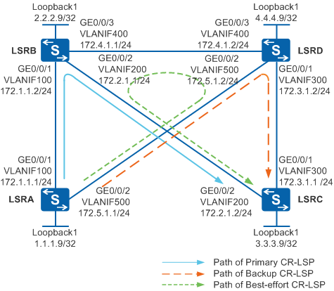
Figure 1 shows an MPLS VPN. A TE tunnel with LSRA as the ingress node and LSRC as the egress node needs to be established on LSRA. A hot-standby CR-LSP and best-effort path also need to be configured.
The path of the primary CR-LSP is LSRA -> LSRB -> LSRC.
The path of the backup CR-LSP is LSRA -> LSRD -> LSRC.
The best-effort path is LSRA -> LSRD -> LSRB -> LSRC.
When the primary CR-LSP fails, traffic switches to the backup CR-LSP. After the primary CR-LSP recovers, traffic switches back to the primary CR-LSP in 15 seconds. If both the primary CR-LSP and backup CR-LSP fail, traffic switches to the best-effort path.

In this scenario, to avoid loops, ensure that all connected interfaces have STP disabled and connected interfaces are removed from VLAN 1. If STP is enabled and VLANIF interfaces of switches are used to construct a Layer 3 ring network, an interface on the network will be blocked. As a result, Layer 3 services on the network cannot run normally.
Configuration Roadmap
The configuration roadmap is as follows:
Assign an IP address to each interface and configure OSPF to ensure that there are reachable routes between LSRs.
Configure an ID for each LSR and globally enable MPLS, MPLS TE, RSVP-TE, CSPF on each node and interface, and enable OSPF TE.
Specify explicit paths for the primary and backup CR-LSPs on LSRA.
Create a tunnel interface with LSRC as the egress node on LSRA, specify an explicit path, configure the hot-standby CR-LSP and best-effort path, and set the WTR time to 15 seconds.
Procedure
- Assign an IP address to each interface and configure OSPF.
# Configure LSRA. Configure IP addresses for interfaces of LSRB, LSRC, and LSRD according to Figure 1. The configurations on LSRB, LSRC, and LSRD are similar to the configuration of LSRA, and are not mentioned here.
<HUAWEI> system-view
[HUAWEI] sysname LSRA
[LSRA] vlan batch 100 500
[LSRA] interface vlanif 100
[LSRA-Vlanif100] ip address 172.1.1.1 255.255.255.0
[LSRA-Vlanif100] quit
[LSRA] interface vlanif 500
[LSRA-Vlanif500] ip address 172.5.1.1 255.255.255.0
[LSRA-Vlanif500] quit
[LSRA] interface gigabitethernet 0/0/1
[LSRA-GigabitEthernet0/0/1] port link-type trunk
[LSRA-GigabitEthernet0/0/1] port trunk allow-pass vlan 100
[LSRA-GigabitEthernet0/0/1] quit
[LSRA] interface gigabitethernet 0/0/2
[LSRA-GigabitEthernet0/0/2] port link-type trunk
[LSRA-GigabitEthernet0/0/2] port trunk allow-pass vlan 500
[LSRA-GigabitEthernet0/0/2] quit
[LSRA] interface loopback 1
[LSRA-LoopBack1] ip address 1.1.1.9 255.255.255.255
[LSRA-LoopBack1] quit
[LSRA] ospf 1
[LSRA-ospf-1] area 0
[LSRA-ospf-1-area-0.0.0.0] network 1.1.1.9 0.0.0.0
[LSRA-ospf-1-area-0.0.0.0] network 172.1.1.0 0.0.0.255
[LSRA-ospf-1-area-0.0.0.0] network 172.5.1.0 0.0.0.255
[LSRA-ospf-1-area-0.0.0.0] quit
[LSRA-ospf-1] quit
After the configurations are complete, run the display ip routing-table command on the LSRs. You can see that the LSRs learn the routes to Loopback1 of each other.
- Configure basic MPLS functions and enable MPLS TE, RSVP-TE, and CSPF.
On each node, enable MPLS TE and RSVP-TE in the MPLS view and in the interface view. Enable CSPF on the ingress node.
# Configure LSRA. The configurations on LSRB, LSRC, and LSRD are similar to the configuration of LSRA, and are not mentioned here. CSPF only needs to be configured on the ingress nodes of the primary tunnel and bypass tunnel. That is, CSPF needs to be enabled on only LSRA.
[LSRA] mpls lsr-id 1.1.1.9
[LSRA] mpls
[LSRA-mpls] mpls te
[LSRA-mpls] mpls rsvp-te
[LSRA-mpls] mpls te cspf
[LSRA-mpls] quit
[LSRA] interface vlanif 100
[LSRA-Vlanif100] mpls
[LSRA-Vlanif100] mpls te
[LSRA-Vlanif100] mpls rsvp-te
[LSRA-Vlanif100] quit
[LSRA] interface vlanif 500
[LSRA-Vlanif500] mpls
[LSRA-Vlanif500] mpls te
[LSRA-Vlanif500] mpls rsvp-te
[LSRA-Vlanif500] quit
- Configure OSPF TE.
# Configure LSRA. The configurations on LSRB, LSRC, and LSRD are similar to the configuration of LSRA, and are not mentioned here.
[LSRA] ospf
[LSRA-ospf-1] opaque-capability enable
[LSRA-ospf-1] area 0
[LSRA-ospf-1-area-0.0.0.0] mpls-te enable
[LSRA-ospf-1-area-0.0.0.0] quit
[LSRA-ospf-1] quit
- Configure the explicit paths for the primary and backup CR-LSPs.
# Configure the explicit path of the primary CR-LSP on LSRA.
[LSRA] explicit-path pri-path
[LSRA-explicit-path-pri-path] next hop 172.1.1.2
[LSRA-explicit-path-pri-path] next hop 172.2.1.2
[LSRA-explicit-path-pri-path] next hop 3.3.3.9
[LSRA-explicit-path-pri-path] quit
# Configure the explicit path of the backup CR-LSP on LSRA.
[LSRA] explicit-path backup-path
[LSRA-explicit-path-backup-path] next hop 172.5.1.2
[LSRA-explicit-path-backup-path] next hop 172.3.1.1
[LSRA-explicit-path-backup-path] next hop 3.3.3.9
[LSRA-explicit-path-backup-path] quit
After the configurations are complete, you can view explicit paths through commands.
[LSRA] display explicit-path pri-path
Path Name : pri-path    Path Status : Enabled
 1      172.1.1.2         Strict      Include
 2      172.2.1.2         Strict      Include
 3      3.3.3.9           Strict      Include
[LSRA] display explicit-path backup-path
Path Name : backup-path  Path Status : Enabled
 1      172.5.1.2         Strict      Include
 2      172.3.1.1         Strict      Include
 3      3.3.3.9           Strict      Include
- Configure a tunnel interface.
# Configure a tunnel interface on LSRA and specify an explicit path.
[LSRA] interface tunnel 1
[LSRA-Tunnel1] ip address unnumbered interface loopback 1
[LSRA-Tunnel1] tunnel-protocol mpls te
[LSRA-Tunnel1] destination 3.3.3.9
[LSRA-Tunnel1] mpls te tunnel-id 100
[LSRA-Tunnel1] mpls te record-route
[LSRA-Tunnel1] mpls te path explicit-path pri-path
# Configure CR-LSP hot standby on the tunnel interface, set the WTR time to 15 seconds, specify an explicit path, and configure the best-effort path.
[LSRA-Tunnel1] mpls te backup hot-standby wtr 15
[LSRA-Tunnel1] mpls te path explicit-path backup-path secondary
[LSRA-Tunnel1] mpls te backup ordinary best-effort
[LSRA-Tunnel1] mpls te commit
[LSRA-Tunnel1] quit
After the configurations are complete, run the display mpls te tunnel-interface tunnel 1 command on LSRA. You can see that the primary and backup CR-LSPs are successfully established.
[LSRA] display mpls te tunnel-interface tunnel 1
    ----------------------------------------------------------------
                               Tunnel1
    ----------------------------------------------------------------
    Tunnel State Desc   :  UP
    Active LSP          :  Primary LSP
    Session ID          :  100
    Ingress LSR ID      :  1.1.1.9          Egress LSR ID:  3.3.3.9
    Admin State         :  UP               Oper State   :  UP
    Primary LSP State      : UP
      Main LSP State       : READY               LSP ID  : 10
    Hot-Standby LSP State  : UP
      Main LSP State       : READY               LSP ID  : 32773
Run the display mpls te hot-standby state interface tunnel 1 command on LSRA to view CR-LSP hot standby information.
[LSRA] display mpls te hot-standby state interface Tunnel 1
(s): same path
---------------------------------------------------------------------
Verbose information about the Tunnel1 hot-standby state
---------------------------------------------------------------------
session id                               : 100
main LSP token                           : 0xc
hot-standby LSP token                    : 0xb
HSB switch result                        : Primary LSP
HSB switch reason                        : -
WTR config time                          : 15s
WTR remain time                          : -
using overlapped path                    : no
Run the ping lsp te command on LSRA to detect connectivity of the hot-standby CR-LSP.[LSRA] ping lsp te tunnel 1 hot-standby LSP PING FEC: TE TUNNEL IPV4 SESSION QUERY Tunnel1 : 100 data bytes, press CTRL_C to break Reply from 3.3.3.9: bytes=100 Sequence=1 time=11 ms Reply from 3.3.3.9: bytes=100 Sequence=2 time=2 ms Reply from 3.3.3.9: bytes=100 Sequence=3 time=2 ms Reply from 3.3.3.9: bytes=100 Sequence=4 time=2 ms Reply from 3.3.3.9: bytes=100 Sequence=5 time=2 ms --- FEC: TE TUNNEL IPV4 SESSION QUERY Tunnel1 ping statistics --- 5 packet(s) transmitted 5 packet(s) received 0.00% packet loss round-trip min/avg/max = 2/3/11 ms
Run the tracert lsp te command on LSRA to check the path of the hot-standby CR-LSP.[LSRA] tracert lsp te tunnel 1 hot-standby LSP Trace Route FEC: TE TUNNEL IPV4 SESSION QUERY Tunnel1 , press CTRL_C to break. TTL Replier Time Type Downstream 0 Ingress 172.5.1.2/[1027 ] 1 172.5.1.2 9 ms Transit 172.3.1.1/[3 ] 2 3.3.3.9 10 ms Egress
- Verify the configuration.
Connect two interfaces, Port 1 and Port 2, on a tester to LSRA and LSRC respectively. On Port 1, inject MPLS traffic and send traffic to Port 2. After the cable attached to GE0/0/1 on LSRA or LSRC is removed, traffic fast switches to the backup CR-LSP at the millisecond level.
# Run the shutdown command on GE0/0/1 of LSRA to simulate cable removal.
[LSRA] interface gigabitethernet 0/0/1
[LSRA-GigabitEthernet0/0/1] shutdown
[LSRA-GigabitEthernet0/0/1] quit
Run the display mpls te tunnel-interface tunnel 1 command on LSRA. You can see that traffic switches to the backup CR-LSP.
[LSRA] display mpls te tunnel-interface tunnel 1
    ----------------------------------------------------------------
                               Tunnel1
    ----------------------------------------------------------------
    Tunnel State Desc   :  UP
    Active LSP          :  Hot-Standby LSP
    Session ID          :  100
    Ingress LSR ID      :  1.1.1.9          Egress LSR ID:  3.3.3.9
    Admin State         :  UP               Oper State   :  UP
    Primary LSP State      : DOWN
      Main LSP State       : SETTING UP
    Hot-Standby LSP State  : UP
      Main LSP State       : READY               LSP ID  : 32773
After attaching the cable into GE0/0/1 (running the undo shutdown command on GE0/0/1 of LSRA), you can see that traffic switches back to the primary CR-LSP in 15 seconds.
After you remove the cable from GE0/0/1 on LSRA or LSRB and the cable from GE0/0/1 on LSRC or LSRD, the tunnel interface goes Down and then Up. This means that the best-effort path has been set up successfully, allowing traffic to switch to the best-effort path.
# Run the shutdown command on GE0/0/1 of LSRA, and then run the shutdown command on GE0/0/1 of LSRC.
[LSRA] interface gigabitethernet 0/0/1
[LSRA-GigabitEthernet0/0/1] shutdown
[LSRA-GigabitEthernet0/0/1] quit
[LSRC] interface gigabitethernet 0/0/1
[LSRC-GigabitEthernet0/0/1] shutdown
[LSRC-GigabitEthernet0/0/1] quit
After 5 seconds, run the display mpls te tunnel-interface tunnel 1 command on LSRA. You can see that the tunnel interface is Up and the best-effort path is successfully established.
[LSRA] display mpls te tunnel-interface tunnel 1
    ----------------------------------------------------------------
                               Tunnel1
    ----------------------------------------------------------------
    Tunnel State Desc   :  UP
    Active LSP          :  Best-Effort LSP
    Session ID          :  100
    Ingress LSR ID      :  1.1.1.9          Egress LSR ID:  3.3.3.9
    Admin State         :  UP               Oper State   :  UP
    Primary LSP State      : DOWN
      Main LSP State       : SETTING UP
    Hot-Standby LSP State  : DOWN
      Main LSP State       : SETTING UP
    Best-Effort LSP State  : UP
      Main LSP State       : READY               LSP ID  : 32776
[LSRA] display mpls te tunnel path
 Tunnel Interface Name : Tunnel1
 Lsp ID : 1.1.1.9 :100 :32776
 Hop Information
  Hop 0   172.5.1.1
  Hop 1   172.5.1.2
  Hop 2   4.4.4.9
  Hop 3   172.4.1.2
  Hop 4   172.4.1.1
  Hop 5   2.2.2.9
  Hop 6   172.2.1.1
  Hop 7   172.2.1.2
  Hop 8   3.3.3.9
Configuration Files
LSRA configuration file
#
sysname LSRA
#
vlan batch 100 500
#
mpls lsr-id 1.1.1.9
mpls
 mpls te
 mpls rsvp-te
 mpls te cspf
#
explicit-path backup-path
 next hop 172.5.1.2
 next hop 172.3.1.1
 next hop 3.3.3.9
#
explicit-path pri-path
 next hop 172.1.1.2
 next hop 172.2.1.2
 next hop 3.3.3.9
#
interface Vlanif100
 ip address 172.1.1.1 255.255.255.0
 mpls
 mpls te
 mpls rsvp-te
#
interface Vlanif500
 ip address 172.5.1.1 255.255.255.0
 mpls
 mpls te
 mpls rsvp-te
#
interface GigabitEthernet0/0/1
 port link-type trunk
 port trunk allow-pass vlan 100
#
interface GigabitEthernet0/0/2
 port link-type trunk
 port trunk allow-pass vlan 500
#
interface LoopBack1
 ip address 1.1.1.9 255.255.255.255
#
interface Tunnel1
 ip address unnumbered interface LoopBack1
 tunnel-protocol mpls te
 destination 3.3.3.9
 mpls te tunnel-id 100
 mpls te record-route
 mpls te path explicit-path pri-path
 mpls te path explicit-path backup-path secondary
 mpls te backup hot-standby mode revertive wtr 15
 mpls te backup ordinary best-effort
 mpls te commit
#
ospf 1
 opaque-capability enable
 area 0.0.0.0
  network 1.1.1.9 0.0.0.0
  network 172.1.1.0 0.0.0.255
  network 172.5.1.0 0.0.0.255
  mpls-te enable
#
return
LSRB configuration file
#
sysname LSRB
#
vlan batch 100 200 400
#
mpls lsr-id 2.2.2.9
mpls
 mpls te
 mpls rsvp-te
#
interface Vlanif100
 ip address 172.1.1.2 255.255.255.0
 mpls
 mpls te
 mpls rsvp-te
#
interface Vlanif200
 ip address 172.2.1.1 255.255.255.0
 mpls
 mpls te
 mpls rsvp-te
#
interface Vlanif400
 ip address 172.4.1.1 255.255.255.0
 mpls
 mpls te
 mpls rsvp-te
#
interface GigabitEthernet0/0/1
 port link-type trunk
 port trunk allow-pass vlan 100
#
interface GigabitEthernet0/0/2
 port link-type trunk
 port trunk allow-pass vlan 200
#
interface GigabitEthernet0/0/3
 port link-type trunk
 port trunk allow-pass vlan 400
#
interface LoopBack1
 ip address 2.2.2.9 255.255.255.255
#
ospf 1
 opaque-capability enable
 area 0.0.0.0
  network 2.2.2.9 0.0.0.0
  network 172.1.1.0 0.0.0.255
  network 172.2.1.0 0.0.0.255
  network 172.4.1.0 0.0.0.255
  mpls-te enable
#
return
LSRC configuration file
#
sysname LSRC
#
vlan batch 200 300
#
mpls lsr-id 3.3.3.9
mpls
 mpls te
 mpls rsvp-te
#
interface Vlanif200
 ip address 172.2.1.2 255.255.255.0
 mpls
 mpls te
 mpls rsvp-te
#
interface Vlanif300
 ip address 172.3.1.1 255.255.255.0
 mpls
 mpls te
 mpls rsvp-te
#
interface GigabitEthernet0/0/1
 port link-type trunk
 port trunk allow-pass vlan 300
#
interface GigabitEthernet0/0/2
 port link-type trunk
 port trunk allow-pass vlan 200
#
interface LoopBack1
 ip address 3.3.3.9 255.255.255.255
#
ospf 1
 opaque-capability enable
 area 0.0.0.0
  network 3.3.3.9 0.0.0.0
  network 172.2.1.0 0.0.0.255
  network 172.3.1.0 0.0.0.255
  mpls-te enable
#
return
LSRD configuration file
#
sysname LSRD
#
vlan batch 300 400 500
#
mpls lsr-id 4.4.4.9
mpls
 mpls te
 mpls rsvp-te
#
interface Vlanif300
 ip address 172.3.1.2 255.255.255.0
 mpls
 mpls te
 mpls rsvp-te
#
interface Vlanif400
 ip address 172.4.1.2 255.255.255.0
 mpls
 mpls te
 mpls rsvp-te
#
interface Vlanif500
 ip address 172.5.1.2 255.255.255.0
 mpls
 mpls te
 mpls rsvp-te
#
interface GigabitEthernet0/0/1
 port link-type trunk
 port trunk allow-pass vlan 300
#
interface GigabitEthernet0/0/2
 port link-type trunk
 port trunk allow-pass vlan 500
#
interface GigabitEthernet0/0/3
 port link-type trunk
 port trunk allow-pass vlan 400
#
interface LoopBack1
 ip address 4.4.4.9 255.255.255.255
#
ospf 1
 opaque-capability enable
 area 0.0.0.0
  network 4.4.4.9 0.0.0.0
  network 172.3.1.0 0.0.0.255
  network 172.4.1.0 0.0.0.255
  network 172.5.1.0 0.0.0.255
  mpls-te enable
#
return