Example for Configuring Dynamic BFD for an MPLS TE Tunnel Protection Group
Networking Requirements
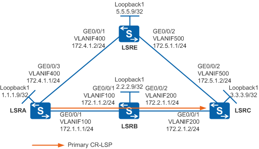
As shown in Figure 1, two MPLS TE tunnels are set up between LSRA and LSRC. An MPLS TE tunnel protection group needs to be configured for the working tunnel. Dynamic BFD is used to detect CR-LSP failures.

In this scenario, to avoid loops, ensure that all connected interfaces have STP disabled and connected interfaces are removed from VLAN 1. If STP is enabled and VLANIF interfaces of switches are used to construct a Layer 3 ring network, an interface on the network will be blocked. As a result, Layer 3 services on the network cannot run normally.
Configuration Roadmap
- Configure an MPLS TE tunnel protection group.
- On the ingress node of the working tunnel, enable active BFD session setup on the tunnel interface. On the egress node of the working tunnel, enable passive BFD session setup in the MPLS view.
Procedure
- Configure an MPLS TE tunnel protection group.
Configure an MPLS TE tunnel protection group by referring to Example for Configuring an MPLS TE Tunnel Protection Group.
- Configure dynamic BFD for the MPLS TE tunnel protection
group.
# Configure LSRA.
[LSRA] bfd
[LSRA-bfd] quit
[LSRA] interface tunnel 1
[LSRA-Tunnel1] mpls te bfd enable
[LSRA-Tunnel1] mpls te bfd min-tx-interval 100 min-rx-interval 100 detect-multiplier 3
[LSRA-Tunnel1] mpls te commit
[LSRA-Tunnel1] quit
# Configure LSRC.
[LSRC] bfd
[LSRC-bfd] mpls-passive
[LSRC-bfd] quit
- Verify the configuration.
Run the display mpls te protection tunnel 100 verbose command on LSRA to check detailed information about the tunnel protection group.
[LSRA] display mpls te protection tunnel 100 verbose
----------------------------------------------------------------
Verbose information about the No.1 protection-group
----------------------------------------------------------------
Work-tunnel id                           : 100
Protect-tunnel id                        : 101
Work-tunnel name                         : Tunnel1
Protect-tunnel name                      : Tunnel2
Work-tunnel reverse-lsp                  : -
Protect-tunnel reverse-lsp               : -
Bridge type                              : 1:1
Switch type                              : unidirectional
Switch result                            : work-tunnel
Tunnel using Best-Effort                 : none
Tunnel using Ordinary                    : none
Work-tunnel frr in use                   : none
Work-tunnel defect state                 : non-defect
Protect-tunnel defect state              : non-defect
Work-tunnel forward-lsp defect state     : non-defect
Protect-tunnel forward-lsp defect state  : non-defect
Work-tunnel reverse-lsp defect state     : non-defect
Protect-tunnel reverse-lsp defect state  : non-defect
HoldOff config time                      : 0ms
HoldOff remain time                      : -
WTR config time                          : 120s
WTR remain time                          : -
Mode                                     : revertive
Using same path                          : -
Local state                              : no request
Far end request                          : no request
# Run the tracert lsp te tunnel 1 command on LSRA to check the path of the working tunnel.
[LSRA] tracert lsp te tunnel 1
  LSP Trace Route FEC: TE TUNNEL IPV4 SESSION QUERY Tunnel1 , press CTRL_C to br
eak.
  TTL   Replier            Time    Type      Downstream
  0                                Ingress   172.1.1.2/[4101 ]
  1     172.1.1.2          7 ms    Transit   172.2.1.2/[3 ]
  2     3.3.3.9            3 ms    Egress
Run the display mpls te protection tunnel all command on LSRA to check information about the tunnel protection group.
[LSRA] display mpls te protection tunnel all
------------------------------------------------------------------------
No. Work-tunnel status  /id  Protect-tunnel status /id    Switch-Result
------------------------------------------------------------------------
1          non-defect   /100        non-defect     /101     work-tunnel
Run the display bfd session all command on LSRA. You can see that the BFD session is in Up state.
[LSRA] display bfd session all
--------------------------------------------------------------------------------
Local Remote     PeerIpAddr      State     Type         InterfaceName
--------------------------------------------------------------------------------
8252  8245       3.3.3.9         Up        D_TE_LSP     Tunnel1
--------------------------------------------------------------------------------
     Total UP/DOWN Session Number : 1/0
# Run the shutdown command on GE0/0/1 of LSRA to simulate a failure of the working tunnel.
[LSRA] interface gigabitethernet 0/0/1
[LSRA-GigabitEthernet0/0/1] shutdown
[LSRA-GigabitEthernet0/0/1] quit
Run the tracert lsp te tunnel 1 command on LSRA again. You can see that traffic has been switched to the protection tunnel.
[LSRA] tracert lsp te tunnel 1
  LSP Trace Route FEC: TE TUNNEL IPV4 SESSION QUERY Tunnel1 , press CTRL_C to br
eak.
  TTL   Replier            Time    Type      Downstream
  0                                Ingress   172.4.1.2/[1028 ]
  1     172.4.1.2          4 ms    Transit   172.5.1.2/[3 ]
  2     3.3.3.9            3 ms    Egress
Run the display mpls te protection tunnel all command on LSRA to check information about the tunnel protection group.
[LSRA] display mpls te protection tunnel all
------------------------------------------------------------------------
No. Work-tunnel status  /id  Protect-tunnel status /id    Switch-Result
------------------------------------------------------------------------
1           in defect   /100        non-defect     /101  protect-tunnel
Configuration File
LSRA configuration file
#
 sysname LSRA
#
vlan batch 100 400
#
bfd
#
mpls lsr-id 1.1.1.9
mpls
 mpls te
 mpls rsvp-te
 mpls te cspf
#
explicit-path backup-path
 next hop 172.4.1.2
 next hop 172.5.1.2
 next hop 3.3.3.9
#
explicit-path pri-path
 next hop 172.1.1.2
 next hop 172.2.1.2
 next hop 3.3.3.9
#
interface Vlanif100
 ip address 172.1.1.1 255.255.255.0
 mpls
 mpls te
 mpls rsvp-te
#
interface Vlanif400
 ip address 172.4.1.1 255.255.255.0
 mpls
 mpls te
 mpls rsvp-te
#
interface GigabitEthernet0/0/1
 port link-type trunk
 port trunk allow-pass vlan 100
#
interface GigabitEthernet0/0/3
 port link-type trunk
 port trunk allow-pass vlan 400
#
interface LoopBack1
 ip address 1.1.1.9 255.255.255.255
#
interface Tunnel1
 ip address unnumbered interface LoopBack1
 tunnel-protocol mpls te
 destination 3.3.3.9
 mpls te tunnel-id 100
 mpls te protection tunnel 101 mode revertive wtr 4
 mpls te bfd enable
 mpls te bfd min-tx-interval 100 min-rx-interval 100
 mpls te path explicit-path pri-path
 mpls te commit
#
interface Tunnel2
 ip address unnumbered interface LoopBack1
 tunnel-protocol mpls te
 destination 3.3.3.9
 mpls te tunnel-id 101
 mpls te path explicit-path backup-path
 mpls te commit
#
ospf 1
 opaque-capability enable
 area 0.0.0.0
  network 1.1.1.9 0.0.0.0
  network 172.1.1.0 0.0.0.255
  network 172.4.1.0 0.0.0.255
  mpls-te enable
#
return
LSRB configuration file
#
 sysname LSRB
#
vlan batch 100 200
#
mpls lsr-id 2.2.2.9
mpls
 mpls te
 mpls rsvp-te
#
interface Vlanif100
 ip address 172.1.1.2 255.255.255.0
 mpls
 mpls te
 mpls rsvp-te
#
interface Vlanif200
 ip address 172.2.1.1 255.255.255.0
 mpls
 mpls te
 mpls rsvp-te
#
interface GigabitEthernet0/0/1
 port link-type trunk
 port trunk allow-pass vlan 100
#
interface GigabitEthernet0/0/2
 port link-type trunk
 port trunk allow-pass vlan 200
#
interface LoopBack1
 ip address 2.2.2.9 255.255.255.255
#
ospf 1
 opaque-capability enable
 area 0.0.0.0
  network 2.2.2.9 0.0.0.0
  network 172.1.1.0 0.0.0.255
  network 172.2.1.0 0.0.0.255
  mpls-te enable
#
return
LSRC configuration file
#
 sysname LSRC
#
vlan batch 200 500
#
bfd
 mpls-passive
#
mpls lsr-id 3.3.3.9
mpls
 mpls te
 mpls rsvp-te
#
interface Vlanif200
 ip address 172.2.1.2 255.255.255.0
 mpls
 mpls te
 mpls rsvp-te
#
interface Vlanif500
 ip address 172.5.1.2 255.255.255.0
 mpls
 mpls te
 mpls rsvp-te
#
interface GigabitEthernet0/0/1
 port link-type trunk
 port trunk allow-pass vlan 200
#
interface GigabitEthernet0/0/2
 port link-type trunk
 port trunk allow-pass vlan 500
#
interface LoopBack1
 ip address 3.3.3.9 255.255.255.255
#
ospf 1
 opaque-capability enable
 area 0.0.0.0
  network 3.3.3.9 0.0.0.0
  network 172.2.1.0 0.0.0.255
  network 172.5.1.0 0.0.0.255
  mpls-te enable
#
return
LSRE configuration file
#
 sysname LSRE
#
vlan batch 400 500
#
mpls lsr-id 5.5.5.9
mpls
 mpls te
 mpls rsvp-te
#
interface Vlanif400
 ip address 172.4.1.2 255.255.255.0
 mpls
 mpls te
 mpls rsvp-te
#
interface Vlanif500
 ip address 172.5.1.1 255.255.255.0
 mpls
 mpls te
 mpls te srlg 2
 mpls rsvp-te
#
interface GigabitEthernet0/0/1
 port link-type trunk
 port trunk allow-pass vlan 400
#
interface GigabitEthernet0/0/2
 port link-type trunk
 port trunk allow-pass vlan 500
#
interface LoopBack1
 ip address 5.5.5.9 255.255.255.255
#
ospf 1
 opaque-capability enable
 area 0.0.0.0
  network 5.5.5.9 0.0.0.0
  network 172.4.1.0 0.0.0.255
  network 172.5.1.0 0.0.0.255
  mpls-te enable
#
return