Example for Configuring a Multicast Static Route to Change the RPF Route
Networking Requirements
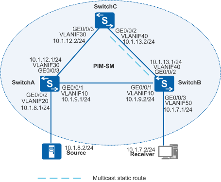
In Figure 1, SwitchA, SwitchB, and SwitchC run Open Shortest Path First (OSPF) to implement IP interworking, and their interfaces use Protocol Independent Multicast - Sparse Mode (PIM-SM) to provide multicast services. Data sent from the multicast source (Source) is forwarded to the receiver host (Receiver) through SwitchA and SwitchB. The link between SwitchA and SwitchB transmits unicast and multicast services simultaneously. To reduce load on this link, multicast data needs to be transmitted along the path SwitchA → SwitchC → SwitchB.

In this scenario, to avoid loops, ensure that all connected interfaces have STP disabled and connected interfaces are removed from VLAN 1. If STP is enabled and VLANIF interfaces of switches are used to construct a Layer 3 ring network, an interface on the network will be blocked. As a result, Layer 3 services on the network cannot run normally.
Configuration Roadmap
By configuring a multicast static route, you can change the reverse path forwarding (RPF) interface used to receive multicast data, so that multicast and unicast services are transmitted through different links to reduce load on a single link. The configuration roadmap is as follows:
Configure IP addresses for interfaces and configure a unicast routing protocol (OSPF in this example) on each switch. Multicast routing protocols depend on unicast routing protocols.
Enable multicast routing on all switches and PIM-SM on all Layer 3 interfaces. Configure a static rendezvous point (RP) and specify the static RP address on all switches. Enable Internet Group Management Protocol (IGMP) on the interface connected to the network segment of the receiver host. After these basic multicast functions are configured, the switches can establish a multicast distribution tree using default parameter settings. Multicast data can then be forwarded to Receiver along the multicast distribution tree.
Configure a multicast RPF static route on SwitchB and specify SwitchC as the RPF neighbor.
Procedure
- Configure IP addresses for interfaces and configure OSPF
on each switch. SwitchB is
used as an example in the following operations. Configurations of
the other switches are similar.
# Create VLANs and add Layer 2 physical interfaces to the VLANs.
<HUAWEI> system-view
[HUAWEI] sysname SwitchB
[SwitchB] vlan batch 10 40 50
[SwitchB] interface gigabitethernet0/0/1
[SwitchB-GigabitEthernet0/0/1] port link-type trunk
[SwitchB-GigabitEthernet0/0/1] port trunk allow-pass vlan 10
[SwitchB-GigabitEthernet0/0/1] quit
[SwitchB] interface gigabitethernet0/0/2
[SwitchB-GigabitEthernet0/0/2] port link-type trunk
[SwitchB-GigabitEthernet0/0/2] port trunk allow-pass vlan 40
[SwitchB-GigabitEthernet0/0/2] quit
[SwitchB] interface gigabitethernet0/0/3
[SwitchB-GigabitEthernet0/0/3] port link-type trunk
[SwitchB-GigabitEthernet0/0/3] port trunk allow-pass vlan 50
[SwitchB-GigabitEthernet0/0/3] quit
# Configure IP addresses and masks for Layer 3 VLANIF interfaces.
[SwitchB] interface vlanif 10
[SwitchB-Vlanif10] ip address 10.1.9.2 24
[SwitchB-Vlanif10] quit
[SwitchB] interface vlanif 40
[SwitchB-Vlanif40] ip address 10.1.13.1 24
[SwitchB-Vlanif40] quit
[SwitchB] interface vlanif 50
[SwitchB-Vlanif50] ip address 10.1.7.1 24
[SwitchB-Vlanif50] quit
# Configure OSPF.
[SwitchB] ospf
[SwitchB-ospf-1] area 0
[SwitchB-ospf-1-area-0.0.0.0] network 10.1.7.0 0.0.0.255
[SwitchB-ospf-1-area-0.0.0.0] network 10.1.9.0 0.0.0.255
[SwitchB-ospf-1-area-0.0.0.0] network 10.1.13.0 0.0.0.255
[SwitchB-ospf-1-area-0.0.0.0] quit
[SwitchB-ospf-1] quit
- Enable multicast routing on all switches and enable PIM-SM
on all Layer 3 interfaces.
# Enable multicast routing globally, PIM-SM on all Layer 3 interfaces, and IGMP on the interface connected to the network segment of the receiver host. (The configurations on the other switches are similar to the configuration on SwitchB.)
[SwitchB] multicast routing-enable
[SwitchB] interface vlanif 10
[SwitchB-Vlanif10] pim sm
[SwitchB-Vlanif10] quit
[SwitchB] interface vlanif 40
[SwitchB-Vlanif40] pim sm
[SwitchB-Vlanif40] quit
[SwitchB] interface vlanif 50
[SwitchB-Vlanif50] pim sm
[SwitchB-Vlanif50] igmp enable
[SwitchB-Vlanif50] quit
# Configure the IP address of VLANIF30 on SwitchC as a static RP address. (The configurations on the other switches are similar to the configuration on SwitchC.)
[SwitchC] pim
[SwitchC-pim] static-rp 10.1.12.2
[SwitchC-pim] quit
# Run the display multicast rpf-info command on SwitchB to check the RPF route to Source. The following command output shows that the RPF route originates from a unicast routing protocol, and the RPF neighbor is SwitchA.
[SwitchB] display multicast rpf-info 10.1.8.2 VPN-Instance: public net RPF information about source: 10.1.8.2 RPF interface: Vlanif10, RPF neighbor: 10.1.9.1 Referenced route/mask: 10.1.8.0/24 Referenced route type: unicast Route selection rule: preference-preferred Load splitting rule: disable - Configure a multicast static route.
# Configure a multicast RPF static route to Source on SwitchB, and configure SwitchC as the RPF neighbor.
[SwitchB] ip rpf-route-static 10.1.8.0 255.255.255.0 10.1.13.2
- Verify the configuration.
# Run the display multicast rpf-info command on SwitchB to check the RPF route to Source. The command output shows that the unicast RPF route has been replaced with the multicast static route and the RPF neighbor has changed to SwitchC.
[SwitchB] display multicast rpf-info 10.1.8.2
VPN-Instance: public net
RPF information about source: 10.1.8.2
     RPF interface: Vlanif40, RPF neighbor: 10.1.13.2
     Referenced route/mask: 10.1.8.0/24
     Referenced route type: mstatic
     Route selection rule: preference-preferred
     Load splitting rule: disable
Configuration Files
SwitchA configuration file
#
sysname SwitchA
#
vlan batch 10 20 30
#
multicast routing-enable
#
interface Vlanif10
 ip address 10.1.9.1 255.255.255.0
 pim sm
#
interface Vlanif20
 ip address 10.1.8.1 255.255.255.0
 pim sm
#
interface Vlanif30
 ip address 10.1.12.1 255.255.255.0
 pim sm
#
interface GigabitEthernet0/0/1
 port link-type trunk
 port trunk allow-pass vlan 10
#
interface GigabitEthernet0/0/2
 port link-type trunk
 port trunk allow-pass vlan 20
#
interface GigabitEthernet0/0/3
 port link-type trunk
 port trunk allow-pass vlan 30
#
ospf 1
 area 0.0.0.0
  network 10.1.8.0 0.0.0.255
  network 10.1.9.0 0.0.0.255
  network 10.1.12.0 0.0.0.255
#
pim
 static-rp 10.1.12.2
#
return
SwitchB configuration file
#
sysname SwitchB
#
vlan batch 10 40 50
#
multicast routing-enable
#
interface Vlanif10
 ip address 10.1.9.2 255.255.255.0
 pim sm
#
interface Vlanif40
 ip address 10.1.13.1 255.255.255.0
 pim sm
#
interface Vlanif50
 ip address 10.1.7.1 255.255.255.0
 pim sm
 igmp enable
#
interface GigabitEthernet0/0/1
 port link-type trunk
 port trunk allow-pass vlan 10
#
interface GigabitEthernet0/0/2
 port link-type trunk
 port trunk allow-pass vlan 40
#
interface GigabitEthernet0/0/3
 port link-type trunk
 port trunk allow-pass vlan 50
#
ospf 1
 area 0.0.0.0
  network 10.1.7.0 0.0.0.255
  network 10.1.9.0 0.0.0.255
  network 10.1.13.0 0.0.0.255
#
pim
 static-rp 10.1.12.2
#
ip rpf-route-static 10.1.8.0 24 10.1.13.2
#
return
SwitchC configuration file
#
sysname SwitchC
#
vlan batch 30 40
#
multicast routing-enable
#
interface Vlanif30
 ip address 10.1.12.2 255.255.255.0
 pim sm
#
interface Vlanif40
 ip address 10.1.13.2 255.255.255.0
 pim sm
#
interface GigabitEthernet0/0/2
 port link-type trunk
 port trunk allow-pass vlan 40
#
interface GigabitEthernet0/0/3
 port link-type trunk
 port trunk allow-pass vlan 30
#
ospf 1
 area 0.0.0.0
  network 10.1.12.0 0.0.0.255
  network 10.1.13.0 0.0.0.255
#
pim
 static-rp 10.1.12.2
#
return