Example for Configuring Multicast Static Routes to Connect RPF Routes
Networking Requirements
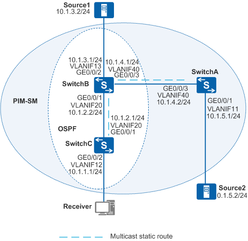
In Figure 1, SwitchB and SwitchC run Open Shortest Path First (OSPF) to implement IP interworking, but they have no unicast route to SwitchA. Switch interfaces must run Protocol Independent Multicast - Sparse Mode (PIM-SM) to provide multicast services. The receiver host (Receiver) can receive data from Source1 and also needs to receive data from Source2.
Configuration Roadmap
An RPF route to Source2 can be established on the path SwitchC → SwitchB → SwitchA by configuring multicast static routes on SwitchB and SwitchC. The configuration roadmap is as follows:
Configure IP addresses for interfaces of the switches. Configure OSPF on SwitchB and SwitchC but not on SwitchA, so that SwitchB and SwitchC have no unicast route to SwitchA.
Enable multicast routing on all switches and PIM-SM on all Layer 3 interfaces. Configure a static RP and specify the static rendezvous point (RP) address on all switches. Enable Internet Group Management Protocol (IGMP) on the interface connected to the network segment of the receiver host. After these basic multicast functions are configured, the switches can establish a multicast distribution tree using default parameter settings. Multicast data can then be forwarded to Receiver along the multicast distribution tree.
Configure multicast static routes to Source2 on SwitchB and SwitchC.
Procedure
- Configure IP addresses for interfaces and configure OSPF on each switch. SwitchB is used as an example in the following operations. Configurations of the other switches are similar.
# Create VLANs and add Layer 2 physical interfaces to the VLANs on the switches.
<HUAWEI> system-view
[HUAWEI] sysname SwitchB
[SwitchB] vlan batch 13 20 40
[SwitchB] interface gigabitethernet0/0/1
[SwitchB-GigabitEthernet0/0/1] port link-type trunk
[SwitchB-GigabitEthernet0/0/1] port trunk allow-pass vlan 20
[SwitchB-GigabitEthernet0/0/1] quit
[SwitchB] interface gigabitethernet0/0/2
[SwitchB-GigabitEthernet0/0/2] port link-type trunk
[SwitchB-GigabitEthernet0/0/2] port trunk allow-pass vlan 13
[SwitchB-GigabitEthernet0/0/2] quit
[SwitchB] interface gigabitethernet0/0/3
[SwitchB-GigabitEthernet0/0/3] port link-type trunk
[SwitchB-GigabitEthernet0/0/3] port trunk allow-pass vlan 40
[SwitchB-GigabitEthernet0/0/3] quit
# Configure IP addresses and masks for Layer 3 VLANIF interfaces on the switches.
[SwitchB] interface vlanif 13
[SwitchB-Vlanif13] ip address 10.1.3.1 24
[SwitchB-Vlanif13] quit
[SwitchB] interface vlanif 20
[SwitchB-Vlanif20] ip address 10.1.2.2 24
[SwitchB-Vlanif20] quit
[SwitchB] interface vlanif 40
[SwitchB-Vlanif40] ip address 10.1.4.1 24
[SwitchB-Vlanif40] quit
# Configure OSPF on SwitchB and SwitchC.
[SwitchB] ospf
[SwitchB-ospf-1] area 0
[SwitchB-ospf-1-area-0.0.0.0] network 10.1.2.0 0.0.0.255
[SwitchB-ospf-1-area-0.0.0.0] network 10.1.3.0 0.0.0.255
[SwitchB-ospf-1-area-0.0.0.0] quit
[SwitchB-ospf-1] quit
- Enable multicast routing on all switches and enable PIM-SM on all Layer 3 interfaces.
# Enable multicast routing globally, PIM-SM on all Layer 3 interfaces, and IGMP on the interface connected to the network segment of the receiver host.
Configure SwitchA.
[SwitchA] multicast routing-enable
[SwitchA] interface vlanif11
[SwitchA-Vlanif11] pim sm
[SwitchA-Vlanif11] quit
[SwitchA] interface vlanif 40
[SwitchA-Vlanif40] pim sm
[SwitchA-Vlanif40] quit
Configure SwitchB.
[SwitchB] multicast routing-enable
[SwitchB] interface vlanif 20
[SwitchB-Vlanif20] pim sm
[SwitchB-Vlanif20] quit
[SwitchB] interface vlanif 13
[SwitchB-Vlanif13] pim sm
[SwitchB-Vlanif13] quit
[SwitchB] interface vlanif 40
[SwitchB-Vlanif40] pim sm
[SwitchB-Vlanif40] quit
Configure SwitchC.
[SwitchC] multicast routing-enable
[SwitchC] interface vlanif 20
[SwitchC-Vlanif20] pim sm
[SwitchC-Vlanif20] quit
[SwitchC] interface vlanif 12
[SwitchC-Vlanif12] pim sm
[SwitchC-Vlanif12] igmp enable
[SwitchC-Vlanif12] quit
# Configure the IP address of VLANIF20 on SwitchB as a static RP address. (The configurations on the other switches are similar to the configuration on SwitchB.)
[SwitchB] pim
[SwitchB-pim] static-rp 10.1.2.2
[SwitchB-pim] quit
# Source1 (10.1.3.2/24) and Source2 (10.1.5.2/24) send multicast data to group G (225.1.1.1). After Receiver joins group G, it receives the multicast data sent by Source1 but cannot receive the multicast data sent by Source2.
# Run the display multicast rpf-info 10.1.5.2 command on SwitchB and SwitchC. No information is displayed, indicating that SwitchB and SwitchC have no RPF route to Source2.
- Configure multicast static routes.
# On SwitchA, configure a static route to the RP to enable Source2 to register on the RP.
[SwitchA] ip route-static 10.1.2.2 32 10.1.4.1
# Configure a multicast RPF static route to Source2 on SwitchB, and configure SwitchA as the RPF neighbor.
[SwitchB] ip rpf-route-static 10.1.5.0 255.255.255.0 10.1.4.2
# Configure a multicast RPF static route to Source2 on SwitchC, and configure SwitchB as the RPF neighbor.
[SwitchC] ip rpf-route-static 10.1.5.0 255.255.255.0 10.1.2.2
- Verify the configuration.
# Run the display multicast rpf-info 10.1.5.2 command on SwitchB and SwitchC to check the RPF route to Source2. The following information is displayed:
[SwitchB] display multicast rpf-info 10.1.5.2
VPN-Instance: public net
RPF information about source: 10.1.5.2
     RPF interface: Vlanif40, RPF neighbor: 10.1.4.2
     Referenced route/mask: 10.1.5.0/24
     Referenced route type: mstatic
     Route selection rule: preference-preferred
     Load splitting rule: disable
[SwitchC] display multicast rpf-info 10.1.5.2 VPN-Instance: public net RPF information about source: 10.1.5.2 RPF interface: Vlanif20, RPF neighbor: 10.1.2.2 Referenced route/mask: 10.1.5.0/24 Referenced route type: mstatic Route selection rule: preference-preferred Load splitting rule: disable# Run the display pim routing-table command on SwitchC to check the PIM routing table. SwitchC has multicast entries for Source2, indicating that Receiver can now receive multicast data from Source2.
[SwitchC] display pim routing-table
 VPN-Instance: public net
 Total 1 (*, G) entry; 2 (S, G) entries

 (*, 225.1.1.1)
     RP: 10.1.2.2
     Protocol: pim-sm, Flag: WC
     UpTime: 03:54:19
     Upstream interface: Vlanif20
         Upstream neighbor: 10.1.2.2
         RPF prime neighbor: 10.1.2.2
     Downstream interface(s) information:
     Total number of downstreams: 1
         1: Vlanif12
             Protocol: igmp, UpTime: 01:38:19, Expires: -

(10.1.3.2, 225.1.1.1)
     RP: 10.1.2.2
     Protocol: pim-sm, Flag: SPT ACT
     UpTime: 00:00:44
     Upstream interface: Vlanif20
         Upstream neighbor: 10.1.2.2
         RPF prime neighbor: 10.1.2.2
     Downstream interface(s) information:
     Total number of downstreams: 1
          1: Vlanif12
              Protocol: pim-sm, UpTime: 00:00:44, Expires: -

(10.1.5.2, 225.1.1.1)
     RP: 10.1.2.2
     Protocol: pim-sm, Flag: SPT ACT
     UpTime: 00:00:44
     Upstream interface: Vlanif20
         Upstream neighbor: 10.1.2.2
         RPF prime neighbor: 10.1.2.2
     Downstream interface(s) information:
     Total number of downstreams: 1
          1: Vlanif12
              Protocol: pim-sm, UpTime: 00:00:44, Expires: -
Configuration Files
SwitchA configuration file
#
sysname SwitchA
#
vlan batch 11 40
#
multicast routing-enable
#
interface Vlanif11
 ip address 10.1.5.1 255.255.255.0
 pim sm
#
interface Vlanif40
 ip address 10.1.4.2 255.255.255.0
 pim sm
#
interface GigabitEthernet0/0/1
 port link-type trunk
 port trunk allow-pass vlan 11
#
interface GigabitEthernet0/0/3
 port link-type trunk
 port trunk allow-pass vlan 40
#
pim
 static-rp 10.1.2.2
#
ip route-static 10.1.2.2 255.255.255.255 10.1.4.1
#
return
SwitchB configuration file
#
sysname SwitchB
#
vlan batch 13 20 40
#
multicast routing-enable
#
interface Vlanif13
 ip address 10.1.3.1 255.255.255.0
 pim sm
#
interface Vlanif20
 ip address 10.1.2.2 255.255.255.0
 pim sm
#
interface Vlanif40
 ip address 10.1.4.1 255.255.255.0
 pim sm
#
interface GigabitEthernet0/0/1
 port link-type trunk
 port trunk allow-pass vlan 20
#
interface GigabitEthernet0/0/2
 port link-type trunk
 port trunk allow-pass vlan 13
#
interface GigabitEthernet0/0/3
 port link-type trunk
 port trunk allow-pass vlan 40
#
ospf 1
 area 0.0.0.0
  network 10.1.2.0 0.0.0.255
  network 10.1.3.0 0.0.0.255
#
pim
 static-rp 10.1.2.2
#
ip rpf-route-static 10.1.5.0 24 10.1.4.2
#
return
SwitchC configuration file
#
sysname SwitchC
#
vlan batch 12 20
#
multicast routing-enable
#
interface Vlanif12
 ip address 10.1.1.1 255.255.255.0
 pim sm
 igmp enable
#
interface Vlanif20
 ip address 10.1.2.1 255.255.255.0
 pim sm
#
interface GigabitEthernet0/0/1
 port link-type trunk
 port trunk allow-pass vlan 20
#
interface GigabitEthernet0/0/2
 port link-type trunk
 port trunk allow-pass vlan 12
#
ospf 1
 area 0.0.0.0
  network 10.1.1.0 0.0.0.255
  network 10.1.2.0 0.0.0.255
#
pim
 static-rp 10.1.2.2
#
ip rpf-route-static 10.1.5.0 24 10.1.2.2
#
return