Example for Configuring MSDP to Implement PIM-SM Inter-domain Multicast Transmission
Networking Requirements
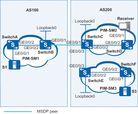
As shown in Figure 1, two autonomous systems (ASs) exist on the network. Each AS contains at least one PIM-SM domain, and each PIM-SM domain contains zero or one multicast source and receiver. The receiver in PIM-SM2 domain wants to receive multicast data from both S3 in PIM-SM3 and S1 in PIM-SM1.
Switch |
Interfaces and IP Addresses |
|---|---|
SwitchA |
|
SwitchB |
|
SwitchC |
|
SwitchD |
|
SwitchE |
|
SwitchF |
|
Configuration Roadmap
Configure MSDP, and set up MSDP peer relationships between RPs in PIM-SM domains to implement inter-domain multicast transmission.
Configure IP addresses for the interfaces on each switch. Configure Open Shortest Path First (OSPF) in the ASs to ensure route reachability within each AS.
Configure External Border Gateway Protocol (EBGP) peers between ASs and import BGP and OSPF routes into each other's routing table to ensure route reachability between ASs.
Enable multicast routing and PIM-SM on each interface. Configure a BootStrap router (BSR) boundary to divide the PIM-SM domain and enable IGMP on interfaces connected to network segments of receiver hosts.
Configure candidate bootstrap routers (C-BSRs) and candidate rendezvous points (C-RPs). Configure the RPs in PIM-SM1 and PIM-SM2 on the autonomous system boundary routers (ASBRs).
Set up MSDP peer relationships between RPs in PIM-SM domains. According to the RPF rule, switches accept SA messages from the next hop destined for the source RP.
Procedure
- Configure IP addresses for interfaces and configure a unicast
routing protocol on each switch.
# According to Figure 1, configure IP addresses and masks for the interfaces on each switch. Configure OSPF between switches. Ensure network connectivity in each AS and enable each switch to update routes using the unicast routing protocol. The configuration details are not mentioned here.
- Configure EBGP peers between ASs and import routes of BGP
and OSPF into each other's routing table.
# Configure EBGP on SwitchB and import OSPF routes to BGP.
[SwitchB] bgp 100
[SwitchB-bgp] router-id 10.1.1.1
[SwitchB-bgp] peer 192.168.2.2 as-number 200
[SwitchB-bgp] ipv4-family multicast
[SwitchB-bgp-af-multicast] peer 192.168.2.2 enable
[SwitchB-bgp-af-multicast] quit
[SwitchB-bgp] import-route ospf 1
[SwitchB-bgp] quit
# Configure EBGP on SwitchC and import OSPF routes to BGP.
[SwitchC] bgp 200
[SwitchC-bgp] router-id 10.2.2.2
[SwitchC-bgp] peer 192.168.2.1 as-number 100
[SwitchC-bgp] ipv4-family multicast
[SwitchC-bgp-af-multicast] peer 192.168.2.1 enable
[SwitchC-bgp-af-multicast] quit
[SwitchC-bgp] import-route ospf 1
[SwitchC-bgp] quit
# Import BGP routes to OSPF on SwitchB. The configuration on SwitchC is similar to the configuration on SwitchB, and is not mentioned here.
[SwitchB] ospf 1
[SwitchB-ospf-1] import-route bgp
[SwitchB-ospf-1] quit
- Enable multicast routing, enable PIM-SM on all interfaces.
Configure a BSR boundary to divide the PIM-SM domain and enable IGMP
on interfaces connected to network segments of receiver hosts.
# Enable multicast routing on SwitchB and enable PIM-SM on each interface. The configurations on other switches are similar to the configuration on SwitchB, and are not mentioned here.
[SwitchB] multicast routing-enable
[SwitchB] interface vlanif 100
[SwitchB-Vlanif100] pim sm
[SwitchB-Vlanif100] quit
[SwitchB] interface vlanif 200
[SwitchB-Vlanif200] pim sm
[SwitchB-Vlanif200] quit
# Configure a BSR boundary on VLANIF200 of SwitchB.
[SwitchB] interface vlanif 200
[SwitchB-Vlanif200] pim bsr-boundary
[SwitchB-Vlanif200] quit
# Configure BSR boundaries on VLANIF200 and VLANIF400 of SwitchC. Configure a BSR boundary on VLANIF400 of SwitchE. The configurations on SwitchC and SwitchE are similar to the configuration on SwitchB, and are not mentioned here.
# Enable IGMP on the interface connecting to SwitchD to the user network segment.
[SwitchD] interface vlanif 102
[SwitchD-Vlanif102] igmp enable
[SwitchD-Vlanif102] quit
- Configure C-BSRs and C-RPs.
# Create a Loopback0 interface, and then configure the C-BSR and C-RP on Loopback0 of SwitchB. The configurations on SwitchC and SwitchE are similar to the configuration on SwitchB, and are not mentioned here.
[SwitchB] interface loopback 0
[SwitchB-LoopBack0] ip address 10.1.1.1 255.255.255.255
[SwitchB-LoopBack0] pim sm
[SwitchB-LoopBack0] quit
[SwitchB] pim
[SwitchB-pim] c-bsr loopback 0
[SwitchB-pim] c-rp loopback 0
[SwitchB-pim] quit
- Configure MSDP peers.
# Configure an MSDP peer on SwitchB.
[SwitchB] msdp
[SwitchB-msdp] peer 192.168.2.2 connect-interface vlanif200
[SwitchB-msdp] quit
# Configure MSDP peers on SwitchC.
[SwitchC] msdp
[SwitchC-msdp] peer 192.168.2.1 connect-interface vlanif200
[SwitchC-msdp] peer 192.168.4.2 connect-interface vlanif400
[SwitchC-msdp] quit
# Configure an MSDP peer on SwitchE.
[SwitchE] msdp
[SwitchE-msdp] peer 192.168.4.1 connect-interface vlanif400
[SwitchE-msdp] quit
- Verify the configuration.
# Run the display bgp peer command to view the BGP peer relationships among switches. The following output shows the BGP peers of SwitchB and SwitchC:
[SwitchB] display bgp peer BGP local router ID : 10.1.1.1 Local AS number : 100 Total number of peers : 1 Peers in established state : 1 Peer V AS MsgRcvd MsgSent OutQ Up/Down State PrefRcv 192.168.2.2 4 200 24 21 0 00:13:09 Established 6[SwitchC] display bgp peer BGP local router ID : 10.2.2.2 Local AS number : 200 Total number of peers : 1 Peers in established state : 1 Peer V AS MsgRcvd MsgSent OutQ Up/Down State PrefRcv 192.168.2.1 4 100 18 16 0 00:12:04 Established 1# Run the display bgp routing-table command to view the BGP routing table on a switch. The following output shows the BGP routing table on SwitchC:
[SwitchC] display bgp routing-table

 BGP Local router ID is 10.2.2.2
 Status codes: * - valid, > - best, d - damped,
               h - history,  i - internal, s - suppressed, S - Stale
               Origin : i - IGP, e - EGP, ? - incomplete


 Total Number of Routes: 22
      Network            NextHop        MED        LocPrf    PrefVal Path/Ogn

 *>   10.1.1.1/32         0.0.0.0         1                     0      ?
 *                       192.168.2.1     0                     0      100?
 *>   10.2.2.2/32         0.0.0.0         0                     0      ?
 *                       192.168.2.1     1                     0      100?
 *>   10.3.3.3/32         0.0.0.0         1                     0      ?
 *                       192.168.2.1     2                     0      100?
 *>   10.110.1.0/24      0.0.0.0         3                     0      ?
 *                       192.168.2.1     2                     0      100?
 *>   10.110.2.0/24      0.0.0.0         2                     0      ?
 *                       192.168.2.1     3                     0      100?
 *>   10.110.3.0/24      0.0.0.0         3                     0      ?
 *                       192.168.2.1     4                     0      100?
 *>   192.168.1.0        0.0.0.0         2                     0      ?
 *                       192.168.2.1     0                     0      100?
 *>   192.168.2.0        0.0.0.0         0                     0      ?
                         192.168.2.1     0                     0      100?
 *>   192.168.3.0        0.0.0.0         0                     0      ?
 *                       192.168.2.1     2                     0      100?
 *>   192.168.4.0        0.0.0.0         0                     0      ?
 *                       192.168.2.1     2                     0      100?
 *>   192.168.5.0        0.0.0.0         2                     0      ?
 *                       192.168.2.1     3                     0      100?
# Run the display msdp brief command to view the status of the MSDP peers on switches. The following output shows summary information about MSDP peers on SwitchB, SwitchC and SwitchE:
[SwitchB] display msdp brief MSDP Peer Brief Information Configured Up Listen Connect Shutdown Down 1 1 0 0 0 0 Peer's Address State Up/Down time AS SA Count Reset Count 192.168.2.2 Up 00:12:27 200 13 0[SwitchC] display msdp brief MSDP Peer Brief Information Configured Up Listen Connect Shutdown Down 2 2 0 0 0 0 Peer's Address State Up/Down time AS SA Count Reset Count 192.168.2.1 Up 01:07:08 100 8 0 192.168.4.2 Up 00:06:39 ? 13 0[SwitchE] display msdp brief MSDP Peer Brief Information Configured Up Listen Connect Shutdown Down 1 1 0 0 0 0 Peer's Address State Up/Down time AS SA Count Reset Count 192.168.4.1 Up 00:15:32 ? 8 0# Run the display msdp peer-status command to view the details about MSDP peers on switches. The following output shows the details about the MSDP peer of SwitchB:
[SwitchB] display msdp peer-status
  MSDP Peer 192.168.2.2, AS 200
  Description:
  Information about connection status:
    State: Up
    Up/down time: 00:15:47
    Resets: 0
    Connection interface: Vlanif200 (192.168.2.1)
    Number of sent/received messages: 16/16
    Number of discarded output messages: 0
    Elapsed time since last connection or counters clear: 00:17:51
  Information about (Source, Group)-based SA filtering policy:
    Import policy: none
    Export policy: none
  Information about SA-Requests:
    Policy to accept SA-Request messages: none
    Sending SA-Requests status: disable
  Minimum TTL to forward SA with encapsulated data: 0
  SAs learned from this peer: 0, SA-cache maximum for the peer: none
  Input queue size: 0, Output queue size: 0
  Counters for MSDP message:
    Count of RPF check failure: 0
    Incoming/outgoing SA messages: 0/0
    Incoming/outgoing SA requests: 0/0
    Incoming/outgoing SA responses: 0/0
    Incoming/outgoing data packets: 0/0
  Peer authentication: unconfigured
  Peer authentication type: none
# Run the display pim routing-table command to view the PIM routing table on a switch. When S1 (10.110.1.2/24) in PIM-SM1 and S3 (10.110.3.2/24) in PIM-SM3 send multicast data to multicast group G (225.1.1.1), Receiver (10.110.2.2/24) in PIM-SM2 receives the multicast data. The following output shows the PIM routing tables on SwitchB and SwitchC:
[SwitchB] display pim routing-table VPN-Instance: public net Total 0 (*, G) entry; 1 (S, G) entry (10.110.1.2, 225.1.1.1) RP: 10.1.1.1 (local) Protocol: pim-sm, Flag: SPT 2MSDP ACT UpTime: 00:00:42 Upstream interface: Vlanif100 Upstream neighbor: 192.168.1.1 RPF prime neighbor: 192.168.1.1 Downstream interface(s) information: Total number of downstreams: 1 1: Vlanif200 Protocol: pim-sm, UpTime: 00:00:42, Expires:-[SwitchC] display pim routing-table VPN-Instance: public net Total 1 (*, G) entry; 2 (S, G) entries (*, 225.1.1.1) RP: 10.2.2.2 (local) Protocol: pim-sm, Flag: WC UpTime: 00:13:46 Upstream interface: Register Upstream neighbor: NULL RPF prime neighbor: NULL Downstream interface(s) information: Total number of downstreams: 1 1: Vlanif300 Protocol: pim-sm, UpTime: 00:13:46, Expires:- (10.110.1.2, 225.1.1.1) RP: 10.2.2.2 (local) Protocol: pim-sm, Flag: SPT MSDP ACT UpTime: 00:00:42 Upstream interface: Vlanif200 Upstream neighbor: 192.168.2.1 RPF prime neighbor: 192.168.2.1 Downstream interface(s) information: Total number of downstreams: 1 1: Vlanif300 Protocol: pim-sm, UpTime: 00:00:42, Expires:- (10.110.3.2, 225.1.1.1) RP: 10.2.2.2 (local) Protocol: pim-sm, Flag: SPT MSDP ACT UpTime: 00:00:42 Upstream interface: Vlanif400 Upstream neighbor: 192.168.4.2 RPF prime neighbor: 192.168.4.2 Downstream interface(s) information: Total number of downstreams: 1 1: Vlanif300 Protocol: pim-sm, UpTime: 00:00:42, Expires:-
Configuration Files
SwitchA configuration file
#
sysname SwitchA
#
vlan batch 100 to 101
#
multicast routing-enable
#
interface Vlanif100
 ip address 192.168.1.1 255.255.255.0
 pim sm
#
interface Vlanif101
 ip address 10.110.1.1 255.255.255.0
 pim sm
#
interface GigabitEthernet0/0/1
 port link-type hybrid
 port hybrid pvid vlan 101
 port hybrid untagged vlan 101
#
interface GigabitEthernet0/0/2
 port link-type trunk
 port trunk allow-pass vlan 100
#
ospf 1
 area 0.0.0.0
  network 10.110.1.0 0.0.0.255
  network 192.168.1.0 0.0.0.255
#
return
SwitchB configuration file
#
sysname SwitchB
#
vlan batch 100 200
#
multicast routing-enable
#
interface Vlanif100
 ip address 192.168.1.2 255.255.255.0
 pim sm
#
interface Vlanif200
 ip address 192.168.2.1 255.255.255.0
 pim bsr-boundary
 pim sm
#
interface GigabitEthernet0/0/1
 port link-type trunk
 port trunk allow-pass vlan 200
#
interface GigabitEthernet0/0/2
 port link-type trunk
 port trunk allow-pass vlan 100
#
interface LoopBack0
 ip address 10.1.1.1 255.255.255.255
 pim sm
#
bgp 100
 router-id 10.1.1.1
 peer 192.168.2.2 as-number 200
 #
 ipv4-family unicast
  undo synchronization
  import-route ospf 1
  peer 192.168.2.2 enable
 #
 ipv4-family multicast
  undo synchronization
  peer 192.168.2.2 enable
#
ospf 1
 import-route bgp
 area 0.0.0.0
  network 10.1.1.1 0.0.0.0
  network 192.168.1.0 0.0.0.255
  network 192.168.2.0 0.0.0.255
#
pim
 c-bsr LoopBack0
 c-rp LoopBack0
#
msdp
 peer 192.168.2.2 connect-interface Vlanif200
#
return
SwitchC configuration file
#
sysname SwitchC
#
vlan batch 200 300 400
#
multicast routing-enable
#
interface Vlanif200
 ip address 192.168.2.2 255.255.255.0
 pim bsr-boundary
 pim sm
#
interface Vlanif300
 ip address 192.168.3.1 255.255.255.0
 pim sm
#
interface Vlanif400
 ip address 192.168.4.1 255.255.255.0
 pim bsr-boundary
 pim sm
#
interface GigabitEthernet0/0/1
 port link-type trunk
 port trunk allow-pass vlan 200
#
interface GigabitEthernet0/0/2
 port link-type trunk
 port trunk allow-pass vlan 300
#
interface GigabitEthernet0/0/3
 port link-type trunk
 port trunk allow-pass vlan 400
#
interface LoopBack0
 ip address 10.2.2.2 255.255.255.255
 pim sm
#
bgp 200
 router-id 10.2.2.2
 peer 192.168.2.1 as-number 100
 #
 ipv4-family unicast
  undo synchronization
  import-route ospf 1
  peer 192.168.2.1 enable
 #
 ipv4-family multicast
  undo synchronization
  peer 192.168.2.1 enable
#
ospf 1
 import-route bgp
 area 0.0.0.0
  network 10.2.2.2 0.0.0.0
  network 192.168.2.0 0.0.0.255
  network 192.168.3.0 0.0.0.255
  network 192.168.4.0 0.0.0.255
#
pim
 c-bsr LoopBack0
 c-rp LoopBack0
#
msdp
 peer 192.168.2.1 connect-interface Vlanif200
 peer 192.168.4.2 connect-interface Vlanif400
#
return
SwitchD configuration file
#
sysname SwitchD
#
vlan batch 102 300
#
multicast routing-enable
#
interface Vlanif102
 ip address 10.110.2.1 255.255.255.0
 pim sm
 igmp enable
#
interface Vlanif300
 ip address 192.168.3.2 255.255.255.0
 pim sm
#
interface GigabitEthernet0/0/1
 port link-type hybrid
 port hybrid pvid vlan 102
 port hybrid untagged vlan 102
#
interface GigabitEthernet0/0/2
 port link-type trunk
 port trunk allow-pass vlan 300
#
ospf 1
 area 0.0.0.0
  network 10.110.2.0 0.0.0.255
  network 192.168.3.0 0.0.0.255
#
return
SwitchE configuration file
#
sysname SwitchE
#
vlan batch 400 500
#
multicast routing-enable
#
interface Vlanif400
 ip address 192.168.4.2 255.255.255.0
 pim bsr-boundary
 pim sm
#
interface Vlanif500
 ip address 192.168.5.1 255.255.255.0
 pim sm
#
interface GigabitEthernet0/0/2
 port link-type trunk
 port trunk allow-pass vlan 500
#
interface GigabitEthernet0/0/3
 port link-type trunk
 port trunk allow-pass vlan 400
#
interface LoopBack0
 ip address 10.3.3.3 255.255.255.255
 pim sm
#
ospf 1
 area 0.0.0.0
  network 10.3.3.3 0.0.0.0
  network 192.168.4.0 0.0.0.255
  network 192.168.5.0 0.0.0.255
#
pim
 c-bsr LoopBack0
 c-rp LoopBack0
#
msdp
 peer 192.168.4.1 connect-interface Vlanif400
#
return
SwitchF configuration file
#
sysname SwitchF
#
vlan batch 103 500
#
multicast routing-enable
#
interface Vlanif103
 ip address 10.110.3.1 255.255.255.0
 pim sm
#
interface Vlanif500
 ip address 192.168.5.2 255.255.255.0
 pim sm
#
interface GigabitEthernet0/0/1
 port link-type hybrid
 port hybrid pvid vlan 103
 port hybrid untagged vlan 103
#
interface GigabitEthernet0/0/2
 port link-type trunk
 port trunk allow-pass vlan 500
#
ospf 1
 area 0.0.0.0
  network 10.110.3.0 0.0.0.255
  network 192.168.5.0 0.0.0.255
#
return