Example for Configuring Static RPF Peers to Implement Inter-AS Multicast Transmission
Networking Requirements
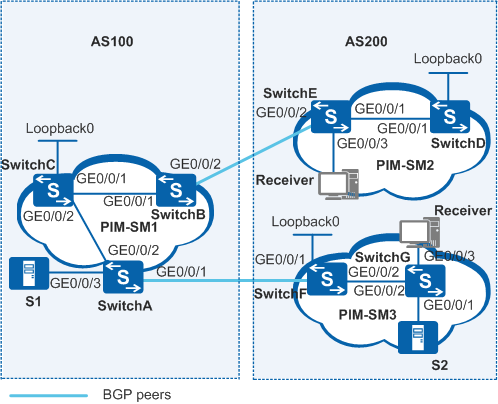
As shown in Figure 1, two autonomous systems (ASs) exist on the network. Each AS contains at least one PIM-SM domain, and each PIM-SM domain contains zero or one multicast source and receiver. Source information needs to be transmitted across PIM-SM domains without changing unicast topology.
Switch |
Interfaces and IP Addresses |
SwitchA |
|
SwitchB |
|
SwitchC |
|
SwitchD |
|
SwitchE |
|
SwitchF |
|
SwitchG |
|
Configuration Roadmap
Configure an MSDP peer on the rendezvous point (RP) in each PIM-SM domain, and specify static RPF peers for the MSDP peers to transmit source information across PIM-SM domains without changing unicast topology.
Configure IP addresses for the interfaces on each switch, configure Open Shortest Path First (OSPF) in the ASs, configure External Border Gateway Protocol (EBGP) between ASs, and import BGP and OSPF routes into each other's routing table.
Enable multicast routing on all switches and PIM-SM on all interfaces, and enable IGMP on interfaces connected to network segments of receiver hosts. Configure Loopback0 interfaces, C-BSRs, and C-RPs on switches. Configure Loopback0 interfaces on SwitchC, SwitchD, and SwitchF as the C-BSR and the C-RP of each PIM-SM domain.
Set up MSDP peer relationships between RPs in PIM-SM domains, namely, between SwitchC and SwitchD, and between SwitchC and SwitchF.
Specify static RPF peers for the MSDP peers. Specify SwitchD and SwitchF as the static RPF peers of SwitchC. Specify SwitchC as the only static RPF peer of SwitchD and SwitchF. According to RPF rules, switches accept SA messages from static RPF peers.
Procedure
- Configure IP addresses for interfaces and configure a unicast
routing protocol on each switch.
# According to Figure 1, configure IP addresses and masks for the interfaces on each switch. Configure OSPF in the ASs. Configure EBGP between SwitchA and SwitchF, and between SwitchB and SwitchE. Import BGP and OSPF routes into each other's routing table. Ensure network connectivity between switches and enable switches to update routes using the unicast routing protocol. The configuration details are not mentioned here.
- Enable multicast routing on all switches and PIM-SM on all interfaces,
and enable IGMP on interfaces connected to network segments of receiver
hosts. In addition, configure the BSR boundary on the interfaces of switches on the AS boundary.
# Enable multicast routing on switches and enable PIM-SM on each interface. The configurations on other switches are similar to the configuration on SwitchC, and are not mentioned here.
[SwitchC] multicast routing-enable
[SwitchC] interface vlanif 100
[SwitchC-Vlanif100] pim sm
[SwitchC-Vlanif100] quit
[SwitchC] interface vlanif 400
[SwitchC-Vlanif400] pim sm
[SwitchC-Vlanif400] quit
# Enable IGMP on VLANIF102 of SwitchE. The configuration on SwitchG is similar to the configuration on SwitchE, and is not mentioned here.
[SwitchE] interface vlanif 102
[SwitchE-Vlanif102] igmp enable
[SwitchE-Vlanif102] quit
# Configure a BSR boundary on VLANIF500 of SwitchA, VLANIF200 of SwitchB, VLANIF200 of SwitchE, and VLANIF500 of SwitchF. The configurations on SwitchB, SwitchE, and SwitchF are similar to the configuration on SwitchA, and are not mentioned here.
[SwitchA] interface vlanif 500
[SwitchA-Vlanif500] pim bsr-boundary
[SwitchA-Vlanif500] quit
- Configure Loopback0 interfaces, C-BSRs, and C-RPs on switches.
# Configure Loopback0 interfaces on SwitchC, SwitchD, and SwitchF. Configure Loopback0 interfaces as C-BSRs and C-RPs. The configurations on SwitchD and SwitchF are similar to the configuration on SwitchC, and are not mentioned here.
[SwitchC] interface loopback 0
[SwitchC-LoopBack0] ip address 10.1.1.1 255.255.255.255
[SwitchC-LoopBack0] pim sm
[SwitchC-LoopBack0] quit
[SwitchC] pim
[SwitchC-pim] c-bsr loopback 0
[SwitchC-pim] c-rp loopback 0
[SwitchC-pim] quit
- Configure static RPF peers.
# Configure SwitchD and SwitchF as the static RPF peers of SwitchC.
[SwitchC] ip ip-prefix list-df permit 192.168.0.0 16 greater-equal 16 less-equal 32
[SwitchC] msdp
[SwitchC-msdp] peer 192.168.3.2 connect-interface vlanif100
[SwitchC-msdp] peer 192.168.5.1 connect-interface vlanif400
[SwitchC-msdp] static-rpf-peer 192.168.3.2 rp-policy list-df
[SwitchC-msdp] static-rpf-peer 192.168.5.1 rp-policy list-df
[SwitchC-msdp] quit
# Configure SwitchC as the only static RPF peer of SwitchD and SwitchF. The configuration on SwitchF is similar to the configuration on SwitchD, and is not mentioned here.
[SwitchD] ip ip-prefix list-c permit 192.168.0.0 16 greater-equal 16 less-equal 32
[SwitchD] msdp
[SwitchD-msdp] peer 192.168.1.1 connect-interface vlanif300
[SwitchD-msdp] static-rpf-peer 192.168.1.1 rp-policy list-c
[SwitchD-msdp] quit
- Verify the configuration.
# Run the display bgp peer command to view BGP peer information on switches. No command output is displayed on SwitchC, which indicates that SwitchC does not set up BGP peer relationship with SwitchD or SwitchF.
# Run the display msdp brief command to view MSDP peer information on switches. When S1 in PIM-SM1 sends multicast data, the receivers in PIM-SM2 and PIM-SM3 domains can receive the data. The following output shows summary information about MSDP peers on SwitchC, SwitchD and SwitchF:
[SwitchC] display msdp brief MSDP Peer Brief Information Configured Up Listen Connect Shutdown Down 2 2 0 0 0 0 Peer's Address State Up/Down time AS SA Count Reset Count 192.168.3.2 Up 01:07:08 ? 8 0 192.168.5.1 Up 00:16:39 ? 13 0[SwitchD] display msdp brief MSDP Peer Brief Information Configured Up Listen Connect Shutdown Down 1 1 0 0 0 0 Peer's Address State Up/Down time AS SA Count Reset Count 192.168.1.1 Up 01:07:09 ? 8 0[SwitchF] display msdp brief MSDP Peer Brief Information Configured Up Listen Connect Shutdown Down 1 1 0 0 0 0 Peer's Address State Up/Down time AS SA Count Reset Count 192.168.4.1 Up 00:16:40 ? 13 0
Configuration Files
SwitchA configuration file
#
sysname SwitchA
#
vlan batch 101 400 500
#
multicast routing-enable
#
interface Vlanif101
 ip address 10.110.1.1 255.255.255.0
 pim sm
#
interface Vlanif400
 ip address 192.168.4.2 255.255.255.0
 pim sm
#
interface Vlanif500
 ip address 192.168.5.2 255.255.255.0
 pim bsr-boundary
 pim sm
#
interface GigabitEthernet0/0/1
 port link-type trunk
 port trunk allow-pass vlan 500
#
interface GigabitEthernet0/0/2
 port link-type trunk
 port trunk allow-pass vlan 400
#
interface GigabitEthernet0/0/3
 port link-type hybrid
 port hybrid pvid vlan 101
 port hybrid untagged vlan 101
#
bgp 100
 router-id 10.1.1.3
 peer 192.168.5.1 as-number 200
#
 ipv4-family unicast
  undo synchronization
  import-route ospf 1
  peer 192.168.5.1 enable
#
ospf 1
 import-route bgp
 area 0.0.0.0
  network 10.110.1.0 0.0.0.255
  network 192.168.4.0 0.0.0.255
  network 192.168.5.0 0.0.0.255
#
return
SwitchB configuration file
#
sysname SwitchB
#
vlan batch 100 200
#
multicast routing-enable
#
interface Vlanif100
 ip address 192.168.1.2 255.255.255.0
 pim sm
#
interface Vlanif200
 ip address 192.168.2.2 255.255.255.0
 pim bsr-boundary
 pim sm
#
interface GigabitEthernet0/0/1
 port link-type trunk
 port trunk allow-pass vlan 100
#
interface GigabitEthernet0/0/2
 port link-type trunk
 port trunk allow-pass vlan 200
#
bgp 100
 router-id 10.1.1.2
 peer 192.168.2.1 as-number 200
#
 ipv4-family unicast
  undo synchronization
  import-route ospf 1
  peer 192.168.2.1 enable
#
ospf 1
 import-route bgp
 area 0.0.0.0
  network 192.168.1.0 0.0.0.255
  network 192.168.2.0 0.0.0.255
#
return
SwitchC configuration file
#
sysname SwitchC
#
vlan batch 100 400
#
multicast routing-enable
#
interface Vlanif100
 ip address 192.168.1.1 255.255.255.0
 pim sm
#
interface Vlanif 400
 ip address 192.168.4.1 255.255.255.0
 pim sm
#
interface GigabitEthernet0/0/1
 port link-type trunk
 port trunk allow-pass vlan 100
#
interface GigabitEthernet0/0/2
 port link-type trunk
 port trunk allow-pass vlan 400
#
interface LoopBack0
 ip address 10.1.1.1 255.255.255.255
 pim sm
#
ospf 1
 area 0.0.0.0
  network 10.1.1.1 0.0.0.0
  network 192.168.1.0 0.0.0.255
  network 192.168.4.0 0.0.0.255
#
pim
 c-bsr LoopBack0
 c-rp LoopBack0
#
msdp
 peer 192.168.3.2 connect-interface Vlanif100
 peer 192.168.5.1 connect-interface Vlanif400
 static-rpf-peer 192.168.5.1 rp-policy list-df
 static-rpf-peer 192.168.3.2 rp-policy list-df
#
ip ip-prefix list-df index 10 permit 192.168.0.0 16 greater-equal 16 less-equal 32
#
return
SwitchD configuration file
#
sysname SwitchD
#
vlan batch 300
#
multicast routing-enable
#
interface Vlanif300
 ip address 192.168.3.2 255.255.255.0
 pim sm
#
interface GigabitEthernet0/0/1
 port link-type trunk
 port trunk allow-pass vlan 300
#
interface LoopBack0
 ip address 10.2.2.2 255.255.255.255
 pim sm
#
ospf 1
 area 0.0.0.0
  network 10.2.2.2 0.0.0.0
  network 192.168.3.0 0.0.0.255
#
pim
 c-bsr LoopBack0
 c-rp LoopBack0
#
ip ip-prefix list-c index 10 permit 192.168.0.0 16 greater-equal 16 less-equal 32
#
msdp
 peer 192.168.1.1 connect-interface Vlanif300
 static-rpf-peer 192.168.1.1 rp-policy list-c
#
return
SwitchE configuration file
#
sysname SwitchE
#
vlan batch 102 200 300
#
multicast routing-enable
#
interface Vlanif102
 ip address 10.110.2.1 255.255.255.0
 pim sm
 igmp enable
#
interface Vlanif200
 ip address 192.168.2.1 255.255.255.0
 pim bsr-boundary
 pim sm
#
interface Vlanif300
 ip address 192.168.3.1 255.255.255.0
 pim sm
#
interface GigabitEthernet0/0/1
 port link-type trunk
 port trunk allow-pass vlan 300
#
interface GigabitEthernet0/0/2
 port link-type trunk
 port trunk allow-pass vlan 200
#
interface GigabitEthernet0/0/3
 port link-type hybrid
 port hybrid pvid vlan 102
 port hybrid untagged vlan 102
#
bgp 200
 router-id 10.2.2.1
 peer 192.168.2.2 as-number 100
#
 ipv4-family unicast
  undo synchronization
  import-route ospf 1
  peer 192.168.2.2 enable
#
ospf 1
 import-route bgp
 area 0.0.0.0
  network 10.110.2.0 0.0.0.255
  network 192.168.2.0 0.0.0.255
  network 192.168.3.0 0.0.0.255
#
return
SwitchF configuration file
#
sysname SwitchF
#
vlan batch 500 600
#
multicast routing-enable
#
interface Vlanif500
 ip address 192.168.5.1 255.255.255.0
 pim bsr-boundary
 pim sm
#
interface Vlanif600
 ip address 192.168.6.1 255.255.255.0
 pim sm
#
interface GigabitEthernet0/0/1
 port link-type trunk
 port trunk allow-pass vlan 500
#
interface GigabitEthernet0/0/2
 port link-type trunk
 port trunk allow-pass vlan 600
#
interface LoopBack0
 ip address 10.3.3.3 255.255.255.255
 pim sm
#
bgp 200
 router-id 10.3.3.3
 peer 192.168.5.2 as-number 100
#
 ipv4-family unicast
  undo synchronization
  import-route ospf 1
  peer 192.168.5.2 enable
#
ospf 1
 import-route bgp
 area 0.0.0.0
  network 10.3.3.3 0.0.0.0
  network 192.168.5.0 0.0.0.255
  network 192.168.6.0 0.0.0.255
#
pim
 c-bsr LoopBack0
 c-rp LoopBack0
#
ip ip-prefix list-c index 10 permit 192.168.0.0 16 greater-equal 16 less-equal 32
#
msdp
 peer 192.168.4.1 connect-interface Vlanif500
 static-rpf-peer 192.168.4.1 rp-policy list-c
#
return
SwitchG configuration file
#
sysname SwitchG
#
vlan batch 103 to 104 600
#
multicast routing-enable
#
interface Vlanif103
 ip address 10.110.3.1 255.255.255.0
 pim sm
#
interface Vlanif104
 ip address 10.110.4.1 255.255.255.0
 pim sm
 igmp enable
#
interface Vlanif600
 ip address 192.168.6.2 255.255.255.0
 pim sm
#
interface GigabitEthernet0/0/1
 port link-type hybrid
 port hybrid pvid vlan 103
 port hybrid untagged vlan 103
#
interface GigabitEthernet0/0/2
 port link-type trunk
 port trunk allow-pass vlan 600
#
interface GigabitEthernet0/0/3
 port link-type hybrid
 port hybrid pvid vlan 104
 port hybrid untagged vlan 104
#
ospf 1
 area 0.0.0.0
  network 10.110.3.0 0.0.0.255
  network 10.110.4.0 0.0.0.255
  network 192.168.6.0 0.0.0.255
#
return