Example for Configuring External Portal Authentication to Control Internal User Access
Networking Requirements
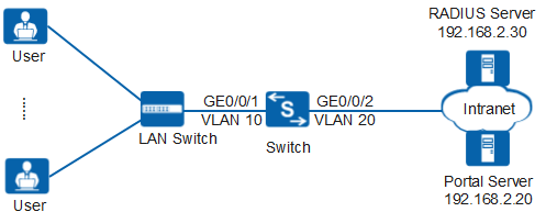
As shown in Figure 1, many users on a company access network through GE0/0/1 of the Switch (used as an access device). After the network operates for a period of time, attacks are detected. The administrator must control network access rights of user terminals to ensure network security. The Switch allows user terminals to access Internet resources only after they are authenticated.
Configuration Roadmap
To control the network access permission of users, the administrator can configure Portal authentication on the Switch after the server with the IP address 192.168.2.30 is used as the RADIUS server, and configure the IP address 192.168.2.20 as the IP address for the Portal server.
The configuration roadmap is as follows (configured on the Switch):
- Create and configure a RADIUS server template, an AAA scheme, and an ISP domain. Bind the RADIUS server template and the AAA scheme to the ISP domain. The Switch can then exchange information with the RADIUS server.
- Configure Portal authentication.
- Create and configure a Portal server template to ensure normal information exchange between the device and the Portal server.
- Enable Portal authentication to authenticate access users.
- Configure a shared key that the device uses to exchange information with the Portal server to improve communication security.

Before configuring this example, ensure that devices can communicate with each other in the network.
Procedure
- Create VLANs and configure the VLAN allowed by the interface to ensure network communication.
# Create VLAN 10 and VLAN 20.
<HUAWEI> system-view
[HUAWEI] sysname Switch
[Switch] vlan batch 10 20
# On the Switch, set GE0/0/1 connecting to users as an access interface, and add GE0/0/1 to VLAN 10.
[Switch] interface gigabitethernet 0/0/1
[Switch-GigabitEthernet0/0/1] port link-type access
[Switch-GigabitEthernet0/0/1] port default vlan 10
[Switch-GigabitEthernet0/0/1] quit
Configure the interface type and VLANs according to the actual situation. In this example, users are added to VLAN 10.
# On the Switch, set GE0/0/2 connecting to the RADIUS server as an access interface, and add GE0/0/2 to VLAN 20.
[Switch] interface gigabitethernet 0/0/2
[Switch-GigabitEthernet0/0/2] port link-type access
[Switch-GigabitEthernet0/0/2] port default vlan 20
[Switch-GigabitEthernet0/0/2] quit
- Create and configure a RADIUS server template, an AAA scheme, and an authentication domain.
# Create and configure RADIUS server template rd1.
[Switch] radius-server template rd1
[Switch-radius-rd1] radius-server authentication 192.168.2.30 1812
[Switch-radius-rd1] radius-server shared-key cipher Huawei@2012
[Switch-radius-rd1] quit
# Create AAA scheme abc and set the authentication mode to RADIUS.
[Switch] aaa
[Switch-aaa] authentication-scheme abc
[Switch-aaa-authen-abc] authentication-mode radius
[Switch-aaa-authen-abc] quit
# Create authentication domain isp1, and bind AAA scheme abc and RADIUS server template rd1 to authentication domain isp1.
[Switch-aaa] domain isp1
[Switch-aaa-domain-isp1] authentication-scheme abc
[Switch-aaa-domain-isp1] radius-server rd1
[Switch-aaa-domain-isp1] quit
[Switch-aaa] quit
# Configure the default domain isp1 in the system view. When a user enters the user name in the format of user@isp1, the user is authenticated in the authentication domain isp1. If the user name does not carry the domain name or carries a nonexistent domain name, the user is authenticated in the default domain.
[Switch] domain isp1# Test whether a user can be authenticated using RADIUS authentication. A user name test@huawei.com and password Huawei2012 have been configured on the RADIUS server.
[Switch] test-aaa test@huawei.com Huawei2012 radius-template rd1 Info: Account test succeeded. - Configure Portal authentication.
# Switch the NAC mode to common mode.
[Switch] undo authentication unified-mode Warning: Switching the authentication mode will take effect after system restart . Some configurations are invalid after the mode is switched. For the invalid co mmands, see the user manual. Save the configuration file and reboot now? [Y/N] y - By default, the NAC unified mode is used.
- After the unified mode is switched to common mode, you must save the configuration and restart the device to make each function in the new configuration mode take effect.
# Create and configure Portal server template abc.
<Switch> system-view
[Switch] web-auth-server abc
[Switch-web-auth-server-abc] server-ip 192.168.2.20
[Switch-web-auth-server-abc] port 50200
[Switch-web-auth-server-abc] url http://192.168.2.20:8080/webagent
[Switch-web-auth-server-abc] quit
Ensure that the port number configured on the device is the same as that used by the Portal server.
# Enable Portal authentication.
[Switch] interface vlanif 10
[Switch-Vlanif10] web-auth-server abc direct
[Switch-Vlanif10] quit
# Set the shared key in cipher text to Huawei@123.
[Switch] web-auth-server abc
[Switch-web-auth-server-abc] shared-key cipher Huawei@123
[Switch-web-auth-server-abc] quit
In this example, users use static IP addresses. If users obtain IP addresses using DHCP and the DHCP server is on the upstream network of the Switch, use the portal free-rule command to create authentication-free rules and ensure that the DHCP server is included in the authentication-free rules.
- Verify the configuration.
- Run the display portal and display web-auth-server configuration commands to check the external Portal authentication configuration. The command output (web-auth-server layer2(direct)) shows that the Portal server template has been bound to the interface vlanif10.
- After starting the browser and entering any network address, the user is redirected to the Portal authentication page. The user then enters the user name and password for authentication.
- If the user name and password are correct, an authentication success message is displayed on the Portal authentication page. The user can access the network.
- After the user goes online, you can run the display access-user command on the device to check the online Portal authentication user information.
Configuration Files
Switch configuration file
#
sysname Switch
#
vlan batch 10 20
undo authentication unified-mode
#
domain isp1
#
radius-server template rd1
 radius-server shared-key cipher %^%#t67cDelRvAQg;*"4@P/3~q_31Sn{ST\V8'Ci633)%^%#
 radius-server authentication 192.168.2.30 1812 weight 80
#
web-auth-server abc
 server-ip 192.168.2.20
 port 50200
 shared-key cipher %^%#t:hJ@gD7<+G&,"Y}Y[VP4\foQ&og/Gg(,J4#\!gD%^%#
 url http://192.168.2.20:8080/webagent
#
aaa
 authentication-scheme abc
  authentication-mode radius
 domain isp1
  authentication-scheme abc
  radius-server rd1
#
interface Vlanif10
 web-auth-server abc direct
#
interface GigabitEthernet0/0/1
 port link-type access
 port default vlan 10
#
interface GigabitEthernet0/0/2
 port link-type access
 port default vlan 20
#
return