Example for Configuring MAC Ping to Detect the Connectivity of a VLAN network
Networking Requirements
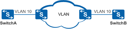
In Figure 1, all devices are on a VLAN network and are enabled with basic Ethernet CFM functions. A MAC ping test instance can be used to detect the connectivity and locate fault of the VLAN network.
Configuration Roadmap
The configuration roadmap is as follows:
Configure a VLAN network and the service environment for starting the NQA test instance.
Configure Ethernet CFM and establish the mapping relationship between CFM and VLAN.
Configure an NQA MAC ping test instance on Switch A, and specify mandatory configurations for the test instance.
Start the NQA MAC ping test instance.
Procedure
- Add Switch A and Switch B to VLAN
10.
# Configure Switch A.
<HUAWEI> system-view[HUAWEI] sysname SwitchA
[SwitchA] vlan 10[SwitchA-vlan10] quit[SwitchA] interface gigabitethernet 0/0/1
[SwitchA-GigabitEthernet0/0/1] port link-type hybrid
[SwitchA-GigabitEthernet0/0/1] port hybrid pvid vlan 10
[SwitchA-GigabitEthernet0/0/1] port hybrid untagged vlan 10
[SwitchA-GigabitEthernet0/0/1] quit
# Configure Switch B.
<HUAWEI> system-view
[HUAWEI] sysname SwitchB
[SwitchB] vlan 10
[SwitchB-vlan10] quit
[SwitchB] interface gigabitethernet 0/0/1
[SwitchB-GigabitEthernet0/0/1] port link-type hybrid
[SwitchB-GigabitEthernet0/0/1] port hybrid pvid vlan 10
[SwitchB-GigabitEthernet0/0/1] port hybrid untagged vlan 10
[SwitchB-GigabitEthernet0/0/1] quit
- Enable basic Ethernet CFM functions between Switch A and Switch B, and establish the mapping
relationship between the MA and VLAN 10.
# Configure Switch A.
[SwitchA] cfm enable[SwitchA] cfm md md1[SwitchA-md-md1] ma ma1[SwitchA-md-md1-ma-ma1] map vlan 10[SwitchA-md-md1-ma-ma1] mep mep-id 1 interface gigabitethernet 0/0/1 outward
[SwitchA-md-md1-ma-ma1] mep ccm-send mep-id 1 enable[SwitchA-md-md1-ma-ma1] remote-mep mep-id 2[SwitchA-md-md1-ma-ma1] remote-mep ccm-receive mep-id 2 enable[SwitchA-md-md1-ma-ma1] quit[SwitchA-md-md1] quit# Configure Switch B.
[SwitchB] cfm enable[SwitchB] cfm md md1[SwitchB-md-md1] ma ma1[SwitchB-md-md1-ma-ma1] map vlan 10[SwitchB-md-md1-ma-ma1] mep mep-id 2 interface gigabitethernet 0/0/1 outward
[SwitchB-md-md1-ma-ma1] mep ccm-send mep-id 2 enable[SwitchB-md-md1-ma-ma1] remote-mep mep-id 1[SwitchB-md-md1-ma-ma1] remote-mep ccm-receive mep-id 1 enable[SwitchB-md-md1-ma-ma1] quit[SwitchB-md-md1] quit
Each interface can be configured with only one MEP and the interface must be a Layer 2 interface.
Run the display cfm remote-mep command on Switch A to view the status of Ethernet CFM. The command output shows that the status of Ethernet CFM is Up.
[SwitchA] display cfm remote-mepThe total number of RMEPs is : 1 The status of RMEPS : 1 up, 0 down, 0 disable -------------------------------------------------- MD Name : md1 Level : 0 MA Name : ma1 RMEP ID : 2 VLAN ID : 10 VSI Name : -- L2VC ID : -- MAC : 00e0-fca4-8ae7 CCM Receive : enabled Trigger-If-Down : disabled CFM Status : up Alarm Status : none Interface TLV : -- Connect Status : up
- Configure a VLAN MAC Ping test instance and start the test
instance.
# Configure Switch A.
[SwitchA] nqa test-instance test macping
[SwitchA-nqa-test-macping] test-type macping
[SwitchA-nqa-test-macping] destination-address remote-mep mep-id 2
[SwitchA-nqa-test-macping] md md1 ma ma1
[SwitchA-nqa-test-macping] mep mep-id 1
# Start the test instance.
[SwitchA-nqa-test-macping] start now - Verify the configuration.
Enter the MAC ping test instance view on Switch A and then run the display nqa results command. You can see that the test result is "success".
[SwitchA-nqa-test-macping] display nqa results

 NQA entry(test, macping) :testflag is inactive ,testtype is macping
  1 . Test 1 result   The test is finished
   SendProbe:3                          ResponseProbe:3
   Completion:success                   RTD OverThresholds number:0
   Min/Max/Avg/Sum RTT:2/36/14/41       RTT Square Sum:1309
   umOfRTT:3                           Drop operation number:0
   Operation sequence errors number:0   RTT Stats errors number:0
   System busy operation number:0       Operation timeout number:0
   Min Positive SD:17                   Min Positive DS:17
   Max Positive SD:17                   Max Positive DS:17
   Positive SD Number:1                 Positive DS Number:1
   Positive SD Sum:17                   Positive DS Sum:17
   Positive SD Square Sum:289           Positive DS Square Sum:289
   Min Negative SD:17                   Min Negative DS:16
   Max Negative SD:17                   Max Negative DS:16
   Negative SD Number:1                 Negative DS Number:1
   Negative SD Sum:17                   Negative DS Sum:16
   Negative SD Square Sum:289           Negative DS Square Sum:256
   Min Delay SD:0                       Min Delay DS:0
   Avg Delay SD:0                       Avg Delay DS:0
   Max Delay SD:0                       Max Delay DS:0
   Packet Loss SD:0                     Packet Loss DS:0
   Packet Loss Unknown:0                Average of Jitter:16
   Average of Jitter SD:17              Average of Jitter DS:16
   Jitter out value:1.0403646           Jitter in value:1.0195313
   NumberOfOWD:0                        OWD SD Sum:0
   OWD DS Sum:0                         TimeStamp unit: ms
   Packet Rewrite Number: 0             Packet Rewrite Ratio: 0%
   Packet Disorder Number: 0            Packet Disorder Ratio: 0%
   Fragment-disorder Number: 0          Fragment-disorder Ratio: 0%
   Start time: --
   End time: --
Configuration Files
SwitchA configuration file
#
sysname SwitchA
#
vlan batch 10
#
cfm enable
#
interface GigabitEthernet0/0/1
 port link-type hybrid
 port hybrid pvid vlan 10
 port hybrid untagged vlan 10
#
cfm md md1
 ma ma1
  map vlan 10
  mep mep-id 1 interface GigabitEthernet0/0/1 outward
  mep ccm-send mep-id 1 enable
  remote-mep mep-id 2
  remote-mep ccm-receive mep-id 2 enable
#
nqa test-instance test macping
 test-type macping
 destination-address remote-mep mep-id 2
 md md1 ma ma1
 mep mep-id 1
#
return
SwitchB configuration file
#
sysname SwitchB
#
vlan batch 10
#
cfm enable
#
interface GigabitEthernet0/0/1
 port link-type hybrid
 port hybrid pvid vlan 10
 port hybrid untagged vlan 10
#
cfm md md1
 ma ma1
  map vlan 10
  mep mep-id 2 interface GigabitEthernet0/0/1 outward
  mep ccm-send mep-id 2 enable
  remote-mep mep-id 1
  remote-mep ccm-receive mep-id 1 enable
#
return