Example for Configuring LSP Jitter Test for a Common Tunnel
Networking Requirements
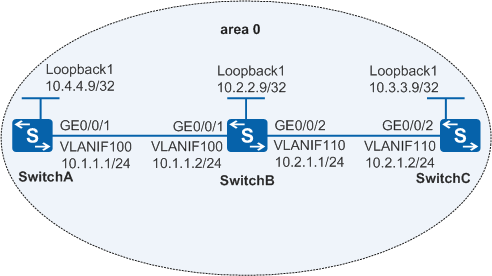
In Figure 1:
The OSPF protocol runs on SwitchA, SwitchB, and SwitchC. They have learned the 32-bit host routes of each other on their loopback interfaces.
MPLS and MPLS LDP are enabled on SwitchA, SwitchB, and SwitchC.
MPLS and MPLS LDP are enabled on VLANIF interfaces on SwitchA, SwitchB, and SwitchC to trigger the establishment of an LDP LSP.
The NQA LSP Jitter test needs to be performed to monitor the jitter between SwitchA and SwitchC.
Configuration Roadmap
The configuration roadmap is as follows:
Configure SwitchA as the NQA client.
Configure SwitchC as the NQA server.
Create an LSP Jitter test instance on SwitchA.
Procedure
- Configure SwitchA, SwitchB, and SwitchC and run OSPF to implement reachable routes between
them.
# Configure SwitchA.
<HUAWEI> system-view
[HUAWEI] sysname SwitchA
[SwitchA] interface loopback 1
[SwitchA-LoopBack1] ip address 10.4.4.9 32
[SwitchA-LoopBack1] quit
[SwitchA] vlan 100
[SwitchA-vlan100] quit
[SwitchA] interface gigabitethernet 0/0/1
[SwitchA-GigabitEthernet0/0/1] port link-type trunk
[SwitchA-GigabitEthernet0/0/1] port trunk allow-pass vlan 100
[SwitchA-GigabitEthernet0/0/1] quit
[SwitchA] interface vlanif 100
[SwitchA-Vlanif100] ip address 10.1.1.1 24
[SwitchA-Vlanif100] quit
[SwitchA] ospf 1
[SwitchA-ospf-1] area 0
[SwitchA-ospf-1-area-0.0.0.0] network 10.1.1.0 0.0.0.255
[SwitchA-ospf-1-area-0.0.0.0] network 10.4.4.9 0.0.0.0
[SwitchA-ospf-1-area-0.0.0.0] quit
[SwitchA-ospf-1] quit
# Configure SwitchB.
<HUAWEI> system-view
[HUAWEI] sysname SwitchB
[SwitchB] interface loopback 1
[SwitchB-LoopBack1] ip address 10.2.2.9 32
[SwitchB-LoopBack1] quit
[SwitchB] vlan 100
[SwitchB-vlan100] quit
[SwitchB] interface gigabitethernet 0/0/1
[SwitchB-GigabitEthernet0/0/1] port link-type trunk
[SwitchB-GigabitEthernet0/0/1] port trunk allow-pass vlan 100
[SwitchB-GigabitEthernet0/0/1] quit
[SwitchB] interface vlanif 100
[SwitchB-Vlanif100] ip address 10.1.1.2 24
[SwitchB-Vlanif100] quit
[SwitchB] vlan 110
[SwitchB-vlan110] quit
[SwitchB] interface gigabitethernet 0/0/2
[SwitchB-GigabitEthernet0/0/2] port link-type trunk
[SwitchB-GigabitEthernet0/0/2] port trunk allow-pass vlan 110
[SwitchB-GigabitEthernet0/0/2] quit
[SwitchB] interface vlanif 110
[SwitchB-Vlanif110] ip address 10.2.1.1 24
[SwitchB-Vlanif110] quit
[SwitchB] ospf 1
[SwitchB-ospf-1] area 0
[SwitchB-ospf-1-area-0.0.0.0] network 10.1.1.0 0.0.0.255
[SwitchB-ospf-1-area-0.0.0.0] network 10.2.1.0 0.0.0.255
[SwitchB-ospf-1-area-0.0.0.0] network 10.2.2.9 0.0.0.0
[SwitchB-ospf-1-area-0.0.0.0] quit
[SwitchB-ospf-1] quit
# Configure SwitchC.
<HUAWEI> system-view
[HUAWEI] sysname SwitchC
[SwitchC] interface loopback 1
[SwitchC-LoopBack1] ip address 10.3.3.9 32
[SwitchC-LoopBack1] quit
[SwitchC] vlan 110
[SwitchC-vlan110] quit
[SwitchC] interface gigabitethernet 0/0/1
[SwitchC-GigabitEthernet0/0/1] port link-type trunk
[SwitchC-GigabitEthernet0/0/1] port trunk allow-pass vlan 110
[SwitchC-GigabitEthernet0/0/1] quit
[SwitchC] interface vlanif 110
[SwitchC-Vlanif110] ip address 10.2.1.2 24
[SwitchC-Vlanif110] quit
[SwitchC] ospf 1
[SwitchC-ospf-1] area 0
[SwitchC-ospf-1-area-0.0.0.0] network 10.2.1.0 0.0.0.255
[SwitchC-ospf-1-area-0.0.0.0] network 10.3.3.9 0.0.0.0
[SwitchC-ospf-1-area-0.0.0.0] quit
[SwitchC-ospf-1] quit
- Configure MPLS LDP on SwitchA, SwitchB, and SwitchC.
# Configure SwitchA.
[SwitchA] mpls lsr-id 10.4.4.9
[SwitchA] mpls
[SwitchA-mpls] quit
[SwitchA] mpls ldp
[SwitchA-mpls-ldp] quit
[SwitchA] interface vlanif 100
[SwitchA-Vlanif100] mpls
[SwitchA-Vlanif100] mpls ldp
[SwitchA-Vlanif100] quit
# Configure SwitchB.
[SwitchB] mpls lsr-id 10.2.2.9
[SwitchB] mpls
[SwitchB-mpls] quit
[SwitchB] mpls ldp
[SwitchB-mpls-ldp] quit
[SwitchB] interface vlanif 100
[SwitchB-Vlanif100] mpls
[SwitchB-Vlanif100] mpls ldp
[SwitchB-Vlanif100] quit
[SwitchB] interface vlanif 110
[SwitchB-Vlanif110] mpls
[SwitchB-Vlanif110] mpls ldp
[SwitchB-Vlanif110] quit
# Configure SwitchC.
[SwitchC] mpls lsr-id 10.3.3.9
[SwitchC] mpls
[SwitchC-mpls] quit
[SwitchC] mpls ldp
[SwitchC-mpls-ldp] quit
[SwitchC] interface vlanif 110
[SwitchC-Vlanif110] mpls
[SwitchC-Vlanif110] mpls ldp
[SwitchC-Vlanif110] quit
- View session information between LDP peers to check whether LDP sessions have been established.
# When the status of an LDP session is Operational, the LDP session is successfully established. The display on SwitchA is used as an example.
[SwitchA] display mpls ldp session LDP Session(s) in Public Network Codes: LAM(Label Advertisement Mode), SsnAge Unit(DDDD:HH:MM) A '*' before a session means the session is being deleted. ------------------------------------------------------------------------------ PeerID Status LAM SsnRole SsnAge KASent/Rcv ------------------------------------------------------------------------------ 10.2.2.9:0 Operational DU Active 0000:00:03 15/15 ------------------------------------------------------------------------------ TOTAL: 1 session(s) Found. - Configure SwitchA as the NQA client.
# Enable the NQA client and create an LDP LSP Jitter test instance.
[SwitchA] nqa test-instance admin lspjitter
[SwitchA-nqa-admin-lspjitter] test-type lspjitter
[SwitchA-nqa-admin-lspjitter] lsp-type ipv4
[SwitchA-nqa-admin-lspjitter] destination-address ipv4 10.3.3.9 lsp-masklen 32 lsp-loopback 127.0.0.1
- Start the test instance.
[SwitchA-nqa-admin-lspjitter] start now - Verify the test result.
# When the network runs stably, verify the test result.
[SwitchA-nqa-admin-lspjitter] display nqa results test-instance admin lspjitter

 NQA entry(admin, lspjitter) :testflag is inactive ,testtype is lspjitter
  1 . Test 1 result   The test is finished
   SendProbe:60                         ResponseProbe:60
   Completion:success                   RTD OverThresholds number:0
   Min/Max/Avg/Sum RTT:3/45/5/296       RTT Square Sum:3284
   NumOfRTT:60                          Drop operation number:0
   Operation sequence errors number:0   RTT Stats errors number:0
   System busy operation number:0       Operation timeout number:0
   Min Positive SD:1                    Max Positive SD:41
   Positive SD Number:9                 Positive SD Sum:53
   Positive SD Square Sum:1705          Min Negative SD:1
   Max Negative SD:41                   Negative SD Number:8
   Negative SD Sum:53                   Negative SD Square Sum:1707
   Packet Loss Unknown:0                Average of Jitter SD:6
   Jitter out value:1.2086132           Packet Loss Ratio: 0%
Configuration Files
SwitchA configuration file
#
sysname SwitchA
#
vlan batch 100
#
mpls lsr-id 10.4.4.9
mpls
#
mpls ldp
#
interface Vlanif100
 ip address 10.1.1.1 255.255.255.0
 mpls
 mpls ldp
#
interface GigabitEthernet0/0/1
 port link-type trunk
 port trunk allow-pass vlan 100
#
interface LoopBack1
 ip address 10.4.4.9 255.255.255.255
#
ospf 1
 area 0.0.0.0
  network 10.1.1.0 0.0.0.255
  network 10.4.4.9 0.0.0.0
#
nqa test-instance admin lspjitter
 test-type lspjitter
 destination-address ipv4 10.3.3.9 lsp-masklen 32 lsp-loopback 127.0.0.1
#
return
SwitchB configuration file
#
sysname SwitchB
#
vlan batch 100 110
#
mpls lsr-id 10.2.2.9
mpls
#
mpls ldp
#
interface Vlanif100
 ip address 10.1.1.2 255.255.255.0
 mpls
 mpls ldp
#
interface Vlanif110
 ip address 10.2.1.1 255.255.255.0
 mpls
 mpls ldp
#
interface GigabitEthernet0/0/1
 port link-type trunk
 port trunk allow-pass vlan 100
#
interface GigabitEthernet0/0/2
 port link-type trunk
 port trunk allow-pass vlan 110
#
interface LoopBack1
 ip address 10.2.2.9 255.255.255.255
#
ospf 1
 area 0.0.0.0
  network 10.1.1.0 0.0.0.255
  network 10.2.1.0 0.0.0.255
  network 10.2.2.9 0.0.0.0
#
return
SwitchC configuration file
#
sysname SwitchC
#
vlan batch 110
#
mpls lsr-id 10.3.3.9
mpls
#
mpls ldp
#
interface Vlanif110
 ip address 10.2.1.2 255.255.255.0
 mpls
 mpls ldp
#
interface GigabitEthernet0/0/1
 port link-type trunk
 port trunk allow-pass vlan 110
#
interface LoopBack1
 ip address 10.3.3.9 255.255.255.255
#
ospf 1
 area 0.0.0.0
  network 10.2.1.0 0.0.0.255
  network 10.3.3.9 0.0.0.0
#
return