Example for Configuring LSP Jitter Test for a TE Tunnel
Networking Requirements
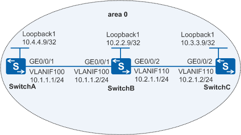
In Figure 1:
The OSPF protocol runs on SwitchA, SwitchB, and SwitchC. They have learned the 32-bit host routes of each other on their loopback interfaces.
MPLS, MPLS TE, and MPLS RSVP-TE are enabled on SwitchA, SwitchB, and SwitchC.
MPLS, MPLS TE, and MPLS RSVP-TE are enabled on the VLANIF interfaces on SwitchA, SwitchB, and SwitchC to set up a TE tunnel from SwitchA to SwitchC.
An NQA LSP Jitter test needs to be performed for the TE tunnel.
Configuration Roadmap
The configuration roadmap is as follows:
Configure SwitchA as the NQA client and create an LSP Jitter test instance on SwitchA.
Configure SwitchC as the NQA server.
Procedure
- Configure SwitchA, SwitchB, and SwitchC and run OSPF to implement reachable routes between
them.
# Configure SwitchA.
<HUAWEI> system-view
[HUAWEI] sysname SwitchA
[SwitchA] interface loopback 1
[SwitchA-LoopBack1] ip address 10.4.4.9 32
[SwitchA-LoopBack1] quit
[SwitchA] vlan 100
[SwitchA-vlan100] quit
[SwitchA] interface gigabitethernet 0/0/1
[SwitchA-GigabitEthernet0/0/1] port link-type trunk
[SwitchA-GigabitEthernet0/0/1] port trunk allow-pass vlan 100
[SwitchA-GigabitEthernet0/0/1] quit
[SwitchA] interface vlanif 100
[SwitchA-Vlanif100] ip address 10.1.1.1 24
[SwitchA-Vlanif100] quit
[SwitchA] ospf 1
[SwitchA-ospf-1] area 0
[SwitchA-ospf-1-area-0.0.0.0] network 10.1.1.0 0.0.0.255
[SwitchA-ospf-1-area-0.0.0.0] network 10.4.4.9 0.0.0.0
[SwitchA-ospf-1-area-0.0.0.0] quit
[SwitchA-ospf-1] quit
# Configure SwitchB.
<HUAWEI> system-view
[HUAWEI] sysname SwitchB
[SwitchB] interface loopback 1
[SwitchB-LoopBack1] ip address 10.2.2.9 32
[SwitchB-LoopBack1] quit
[SwitchB] vlan 100
[SwitchB-vlan100] quit
[SwitchB] interface gigabitethernet 0/0/1
[SwitchB-GigabitEthernet0/0/1] port link-type trunk
[SwitchB-GigabitEthernet0/0/1] port trunk allow-pass vlan 100
[SwitchB-GigabitEthernet0/0/1] quit
[SwitchB] interface vlanif 100
[SwitchB-Vlanif100] ip address 10.1.1.2 24
[SwitchB-Vlanif100] quit
[SwitchB] vlan 110
[SwitchB-vlan110] quit
[SwitchB] interface gigabitethernet 0/0/2
[SwitchB-GigabitEthernet0/0/2] port link-type trunk
[SwitchB-GigabitEthernet0/0/2] port trunk allow-pass vlan 110
[SwitchB-GigabitEthernet0/0/2] quit
[SwitchB] interface vlanif 110
[SwitchB-Vlanif110] ip address 10.2.1.1 24
[SwitchB-Vlanif110] quit
[SwitchB] ospf 1
[SwitchB-ospf-1] area 0
[SwitchB-ospf-1-area-0.0.0.0] network 10.1.1.0 0.0.0.255
[SwitchB-ospf-1-area-0.0.0.0] network 10.2.1.0 0.0.0.255
[SwitchB-ospf-1-area-0.0.0.0] network 10.2.2.9 0.0.0.0
[SwitchB-ospf-1-area-0.0.0.0] quit
[SwitchB-ospf-1] quit
# Configure SwitchC.
<HUAWEI> system-view
[HUAWEI] sysname SwitchC
[SwitchC] interface loopback 1
[SwitchC-LoopBack1] ip address 10.3.3.9 32
[SwitchC-LoopBack1] quit
[SwitchC] vlan 110
[SwitchC-vlan110] quit
[SwitchC] interface gigabitethernet 0/0/1
[SwitchC-GigabitEthernet0/0/1] port link-type trunk
[SwitchC-GigabitEthernet0/0/1] port trunk allow-pass vlan 110
[SwitchC-GigabitEthernet0/0/1] quit
[SwitchC] interface vlanif 110
[SwitchC-Vlanif110] ip address 10.2.1.2 24
[SwitchC-Vlanif110] quit
[SwitchC] ospf 1
[SwitchC-ospf-1] area 0
[SwitchC-ospf-1-area-0.0.0.0] network 10.2.1.0 0.0.0.255
[SwitchC-ospf-1-area-0.0.0.0] network 10.3.3.9 0.0.0.0
[SwitchC-ospf-1-area-0.0.0.0] quit
[SwitchC-ospf-1] quit
- Configure MPLS RSVP-TE on SwitchA, SwitchB, and SwitchC.
# Configure SwitchA.
[SwitchA] mpls lsr-id 10.4.4.9
[SwitchA] mpls
[SwitchA-mpls] mpls te
[SwitchA-mpls] mpls rsvp-te
[SwitchA-mpls] mpls te cspf
[SwitchA-mpls] quit
[SwitchA] interface vlanif 100
[SwitchA-Vlanif100] mpls
[SwitchA-Vlanif100] mpls te
[SwitchA-Vlanif100] mpls rsvp-te
[SwitchA-Vlanif100] quit
[SwitchA] interface Tunnel1
[SwitchA-Tunnel1] ip address unnumbered interface LoopBack1
[SwitchA-Tunnel1] tunnel-protocol mpls te
[SwitchA-Tunnel1] destination 10.3.3.9
[SwitchA-Tunnel1] mpls te tunnel-id 100
[SwitchA-Tunnel1] mpls te commit
[SwitchA-Tunnel1] quit
[SwitchA] ospf 1
[SwitchA-ospf-1] opaque-capability enable
[SwitchA-ospf-1] area 0
[SwitchA-ospf-1-area-0.0.0.0] mpls-te enable
[SwitchA-ospf-1-area-0.0.0.0] quit
[SwitchA-ospf-1] quit
# Configure SwitchB.
[SwitchB] mpls lsr-id 10.2.2.9
[SwitchB] mpls
[SwitchB-mpls] mpls te
[SwitchB-mpls] mpls rsvp-te
[SwitchB-mpls] quit
[SwitchB] interface vlanif 100
[SwitchB-Vlanif100] mpls
[SwitchB-Vlanif100] mpls te
[SwitchB-Vlanif100] mpls rsvp-te
[SwitchB-Vlanif100] quit
[SwitchB] interface vlanif 110
[SwitchB-Vlanif110] mpls
[SwitchB-Vlanif110] mpls te
[SwitchB-Vlanif110] mpls rsvp-te
[SwitchB-Vlanif110] quit
[SwitchB] ospf 1
[SwitchB-ospf-1] opaque-capability enable
[SwitchB-ospf-1] area 0
[SwitchB-ospf-1-area-0.0.0.0] mpls-te enable
[SwitchB-ospf-1-area-0.0.0.0] quit
[SwitchB-ospf-1] quit
# Configure SwitchC.
[SwitchC] mpls lsr-id 10.3.3.9
[SwitchC] mpls
[SwitchC-mpls] mpls te
[SwitchC-mpls] mpls rsvp-te
[SwitchC-mpls] quit
[SwitchC] interface vlanif 110
[SwitchC-Vlanif110] mpls
[SwitchC-Vlanif110] mpls te
[SwitchC-Vlanif110] mpls rsvp-te
[SwitchC-Vlanif110] quit
[SwitchC] interface Tunnel1
[SwitchC-Tunnel1] ip address unnumbered interface LoopBack1
[SwitchC-Tunnel1] tunnel-protocol mpls te
[SwitchC-Tunnel1] destination 10.4.4.9
[SwitchC-Tunnel1] mpls te tunnel-id 100
[SwitchC-Tunnel1] mpls te commit
[SwitchC-Tunnel1] quit
[SwitchC] ospf 1
[SwitchC-ospf-1] opaque-capability enable
[SwitchC-ospf-1] area 0
[SwitchC-ospf-1-area-0.0.0.0] mpls-te enable
[SwitchC-ospf-1-area-0.0.0.0] quit
[SwitchC-ospf-1] quit
- View the status of the TE tunnel.
The display on SwitchA is used as an example.
[SwitchA] display mpls te tunnel-interface ---------------------------------------------------------------- Tunnel1 ---------------------------------------------------------------- Tunnel State Desc : UP Active LSP : Primary LSP Session ID : 25 Ingress LSR ID : 10.4.4.9 Egress LSR ID: 10.3.3.9 Admin State : UP Oper State : UP Primary LSP State : UP Main LSP State : READY LSP ID : 4 - Create an NQA test instance on SwitchA.
# Enable the NQA client and create an LSP Jitter test instance for the TE tunnel.
[SwitchA] nqa test-instance admin lspjitter
[SwitchA-nqa-admin-lspjitter] test-type lspjitter
[SwitchA-nqa-admin-lspjitter] lsp-type te
[SwitchA-nqa-admin-lspjitter] lsp-tetunnel tunnel 1
- Start the test instance.
[SwitchA-nqa-admin-lspjitter] start now - Verify the test result.
# When the network runs stably, verify the test result.
[SwitchA-nqa-admin-lspjitter] display nqa results test-instance admin lspjitter

 NQA entry(admin, lspjitter) :testflag is inactive ,testtype is lspjitter
  1 . Test 1 result   The test is finished
   SendProbe:60                         ResponseProbe:60
   Completion:success                   RTD OverThresholds number:0
   Min/Max/Avg/Sum RTT:3/32/5/311       RTT Square Sum:3041
   NumOfRTT:60                          Drop operation number:0
   Operation sequence errors number:0   RTT Stats errors number:0
   System busy operation number:0       Operation timeout number:0
   Min Positive SD:1                    Max Positive SD:28
   Positive SD Number:9                 Positive SD Sum:74
   Positive SD Square Sum:1376          Min Negative SD:1
   Max Negative SD:28                   Negative SD Number:11
   Negative SD Sum:78                   Negative SD Square Sum:1374
   Packet Loss Unknown:0                Average of Jitter SD:7
   Jitter out value:2.1726604           Packet Loss Ratio: 0%
Configuration Files
SwitchA configuration file
#
sysname SwitchA
#
vlan batch 100
#
mpls lsr-id 10.4.4.9
mpls
 mpls te
 mpls rsvp-te
 mpls te cspf
#
interface Vlanif100
 ip address 10.1.1.1 255.255.255.0
 mpls
 mpls te
 mpls rsvp-te
#
interface GigabitEthernet0/0/1
 port link-type trunk
 port trunk allow-pass vlan 100
#
interface LoopBack1
 ip address 10.4.4.9 255.255.255.255
#
interface Tunnel1
 ip address unnumbered interface LoopBack1
 tunnel-protocol mpls te
 destination 10.3.3.9
 mpls te tunnel-id 100
 mpls te commit
#
ospf 1
 opaque-capability enable
 area 0.0.0.0
  network 10.1.1.0 0.0.0.255
  network 10.4.4.9 0.0.0.0
  mpls-te enable
#
nqa test-instance admin lspjitter
 test-type lspjitter
 lsp-type te
 lsp-tetunnel Tunnel1
#
return
SwitchB configuration file
#
sysname SwitchB
#
vlan batch 100 110
#
mpls lsr-id 10.2.2.9
mpls
 mpls te
 mpls rsvp-te
#
interface Vlanif100
 ip address 10.1.1.2 255.255.255.0
 mpls
 mpls te
 mpls rsvp-te
#
interface Vlanif110
 ip address 10.2.1.1 255.255.255.0
 mpls
 mpls te
 mpls rsvp-te
#
interface GigabitEthernet0/0/1
 port link-type trunk
 port trunk allow-pass vlan 100
#
interface GigabitEthernet0/0/2
 port link-type trunk
 port trunk allow-pass vlan 110
#
interface LoopBack1
 ip address 10.2.2.9 255.255.255.255
#
ospf 1
 opaque-capability enable
 area 0.0.0.0
  network 10.1.1.0 0.0.0.255
  network 10.2.1.0 0.0.0.255
  network 10.2.2.9 0.0.0.0
  mpls-te enable
#
return
SwitchC configuration file
#
sysname SwitchC
#
vlan batch 110
#
mpls lsr-id 10.3.3.9
mpls
 mpls te
 mpls rsvp-te
#
interface Vlanif110
 ip address 10.2.1.2 255.255.255.0
 mpls
 mpls te
 mpls rsvp-te
#
interface GigabitEthernet0/0/2
 port link-type trunk
 port trunk allow-pass vlan 110
#
interface LoopBack1
 ip address 10.3.3.9 255.255.255.255
#
interface Tunnel1
 ip address unnumbered interface LoopBack1
 tunnel-protocol mpls te
 destination 10.4.4.9
 mpls te tunnel-id 100
 mpls te commit
#
ospf 1
 opaque-capability enable
 area 0.0.0.0
  network 10.2.1.0 0.0.0.255
  network 10.3.3.9 0.0.0.0
  mpls-te enable
#
return