Example for Configuring the LSP Trace Test for Checking the CR-LSP Hot Standby Tunnel
Networking Requirements
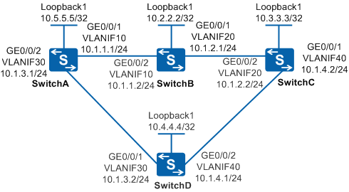
In the MPLS VPN shown in Figure 1, a TE tunnel with Switch C being the egress is set up on Switch A, and CR-LSP hot standby is configured on the TE tunnel.
OSPF is configured on SwitchA, SwitchB, SwitchC, and SwitchD to enable them to learn the 32-bit host addresses of the loopback interfaces from each other.
MPLS, MPLS TE, and MPLS RSVP-TE are enabled on SwitchA, SwitchB, SwitchC, and SwitchD.
MPLS, MPLS TE, and MPLS RSVP-TE are enabled on the interfaces connected to Switch A, Switch B, and Switch C. Then, a TE tunnel is set up from SwitchA to SwitchC.
- The primary CR-LSP is Switch A-Switch B-Switch C.
- The hot standby CR-LSP is Switch A-Switch D-Switch C.
But if the hot standby CR-LSP is faulty and therefore is unable to carry the traffic that is switched from the primary CR-LSP, the hot standby CR-LSP needs to be detected. NQA LSP Trace can be used to detect the connectivity of the hot standby CR-LSP. This function can detect the connectivity of the hot standby CR-LSP and its performance in real time. This helps detect and identify faults on the hot standby CR-LSP.

In this scenario, ensure that all connected interfaces have STP disabled. If STP is enabled and VLANIF interfaces of switches are used to construct a Layer 3 ring network, an interface on the network may be blocked. As a result, Layer 3 services on the network cannot run normally.
Configuration Roadmap
The configuration roadmap is as follows:
Configure SwitchA as the NQA client and create an LSP Trace test instance on Switch A.
Configure SwitchC as the NQA server.
Procedure
- Configure routes among SwitchA, SwitchB, SwitchC, and SwitchD.
For detailed configuration, see the configuration files in this example.
- Configure MPLS RSVP-TE on SwitchA, SwitchB, SwitchC, and SwitchD.
For detailed configuration, see the configuration files in this example.
- On SwitchA, set up a TE tunnel to SwitchC.
For detailed configuration, see the configuration files in this example.
- Configure an NQA test instance on SwitchA.
# Enable the NQA client and create an LSP Trace test instance for checking the TE tunnel.
<HUAWEI> system-view
[HUAWEI] sysname SwitchA
[SwitchA] nqa test-instance admin lsptrace[SwitchA-nqa-admin-lsptrace] test-type lsptrace[SwitchA-nqa-admin-lsptrace] lsp-type te[SwitchA-nqa-admin-lsptrace] lsp-tetunnel tunnel 1 hot-standby
- Start the test.
[SwitchA-nqa-admin-lsptrace] start now - Verify the configuration.
[SwitchA-nqa-admin-lsptrace] display nqa results test-instance admin lsptraceNQA entry(admin, lsptrace) :testflag is inactive ,testtype is lsptrace 1 . Test 1 result The test is finished Completion:success Attempts number:1 Disconnect operation number:0 Operation timeout number:0 System busy operation number:0 Connection fail number:0 Operation sequence errors number:0 RTT Status errors number:0 Drop operation number:0 Last good path Time:2009-04-24 11:22:21.2 1 . Hop 1 Send operation times: 3 Receive response times: 3 Min/Max/Average Completion Time: 50/60/56 Sum/Square-Sum Completion Time: 170/9700 RTD OverThresholds number: 0 Last Good Probe Time: 2009-04-24 11:22:20.8 Destination ip address:10.1.3.2 Lost packet ratio: 0 % 2 . Hop 2 Send operation times: 3 Receive response times: 3 Min/Max/Average Completion Time: 80/110/93 Sum/Square-Sum Completion Time: 280/26600 RTD OverThresholds number: 0 Last Good Probe Time: 2009-04-24 11:22:21.2 Destination ip address:10.3.3.3 Lost packet ratio: 0 %
Configuration Files
SwitchA configuration file
#
sysname SwitchA
#
vlan batch 10 30
#
mpls lsr-id 10.5.5.5
mpls
 mpls te
 mpls rsvp-te
 mpls te cspf
#
explicit-path backup
 next hop 10.1.3.2
 next hop 10.1.4.2
 next hop 10.3.3.3
#
explicit-path main
 next hop 10.1.1.2
 next hop 10.1.2.2
 next hop 10.3.3.3
#
interface Vlanif10
 ip address 10.5.5.5 255.255.255.0
 mpls
 mpls te
 mpls rsvp-te
#
interface Vlanif30
 ip address 10.1.3.1 255.255.255.0
 mpls
 mpls te
 mpls rsvp-te
#
interface  GigabitEthernet0/0/1
 port link-type hybrid
 port hybrid pvid vlan 10
 port hybrid untagged vlan 10
#
interface  GigabitEthernet0/0/2
 port link-type hybrid
 port hybrid pvid vlan 30
 port hybrid untagged vlan 30
#
interface LoopBack1
 ip address 10.5.5.5 255.255.255.255
#
interface Tunnel1
 ip address unnumbered interface LoopBack1
 tunnel-protocol mpls te
 destination 10.3.3.3
 mpls te tunnel-id 100
 mpls te record-route
 mpls te path explicit-path main
 mpls te path explicit-path backup secondary
 mpls te backup hot-standby mode revertive wtr 15
 mpls te backup ordinary best-effort
 mpls te commit
#
ospf 1
 opaque-capability enable
 area 0.0.0.0
  network 10.1.1.0 0.0.0.255
  network 10.5.5.5 0.0.0.0
  network 10.1.3.0 0.0.0.255
  mpls-te enable
#
nqa test-instance admin lsptrace
 test-type lsptrace
 lsp-type te
 lsp-tetunnel Tunnel1 hot-standby
#
return
SwitchB configuration file
#
sysname SwitchB
#
vlan batch 10 20
#
mpls lsr-id 10.2.2.2
mpls
 mpls te
 mpls rsvp-te
 mpls te cspf
#
interface Vlanif10
 ip address 10.1.1.2 255.255.255.0
 mpls
 mpls te
 mpls rsvp-te
#
interface Vlanif20
 ip address 10.1.2.1 255.255.255.0
 mpls
 mpls te
 mpls rsvp-te
#
interface  GigabitEthernet0/0/1
 port link-type hybrid
 port hybrid pvid vlan 20
 port hybrid untagged vlan 20
#
interface  GigabitEthernet0/0/2
 port link-type hybrid
 port hybrid pvid vlan 10
 port hybrid untagged vlan 10
#
interface LoopBack1
 ip address 10.2.2.2 255.255.255.255
#
ospf 1
 opaque-capability enable
 area 0.0.0.0
  network 10.1.1.0 0.0.0.255
  network 10.2.2.2 0.0.0.0
  network 10.1.2.0 0.0.0.255
  mpls-te enable
#
return
SwitchC configuration file
#
sysname SwitchC
#
vlan batch 20 40
#
mpls lsr-id 10.3.3.3
mpls
 mpls te
 mpls rsvp-te
 mpls te cspf
#
interface Vlanif20
 ip address 10.1.2.2 255.255.255.0
 mpls
 mpls te
 mpls rsvp-te
#
interface Vlanif40
 ip address 10.1.4.2 255.255.255.0
 mpls
 mpls te
 mpls rsvp-te
#
interface  GigabitEthernet0/0/1
 port link-type hybrid
 port hybrid pvid vlan 40
 port hybrid untagged vlan 40
#
interface  GigabitEthernet0/0/2
 port link-type hybrid
 port hybrid pvid vlan 20
 port hybrid untagged vlan 20
#
interface LoopBack1
 ip address 10.3.3.3 255.255.255.255
#
ospf 1
 opaque-capability enable
 area 0.0.0.0
  network 10.1.2.0 0.0.0.255
  network 10.1.4.0 0.0.0.255
  network 10.3.3.3 0.0.0.0
  mpls-te enable
#
return
SwitchD configuration file
#
sysname SwitchD
#
vlan batch 30 40
#
mpls lsr-id 10.4.4.4
mpls
 mpls te
 mpls rsvp-te
 mpls te cspf
#
interface Vlanif30
 ip address 10.1.3.2 255.255.255.0
 mpls
 mpls te
 mpls rsvp-te
#
interface Vlanif40
 ip address 10.1.4.1 255.255.255.0
 mpls
 mpls te
 mpls rsvp-te
#
interface  GigabitEthernet0/0/1
 port link-type hybrid
 port hybrid pvid vlan 30
 port hybrid untagged vlan 30
#
interface  GigabitEthernet0/0/2
 port link-type hybrid
 port hybrid pvid vlan 40
 port hybrid untagged vlan 40
#
interface LoopBack1
 ip address 10.4.4.4 255.255.255.255
#
ospf 1
 opaque-capability enable
 area 0.0.0.0
  network 10.4.4.4 0.0.0.0
  network 10.1.3.0 0.0.0.255
  network 10.1.4.0 0.0.0.255
  mpls-te enable
#
return