Example for Configuring the PWE3 Ping Test on a Single-Hop PW
Networking Requirements
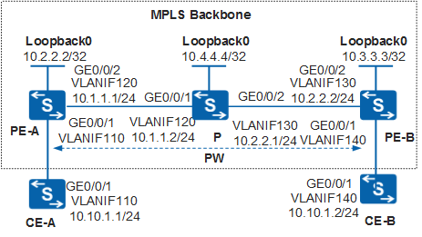
In Figure 1, CE-A and CE-B are connected to PE-A and PE-B respectively. PE-A and PE-B are connected through the MPLS backbone network. A dynamic PW needs to be set up between PE-A and PE-B through the LSP tunnel.
The PWE3 Ping function of the single-hop PW needs to be performed to test the connectivity of the PW between PE-A and PE-B.
Configuration Roadmap
The configuration roadmap is as follows:
Run the IGP protocol on the backbone network to make the routes between Switches on the backbone network reachable.
Configure the basic MPLS functions on the backbone network and set up an LSP tunnel. Set up the MPLS LDP peer relationship between the two PE devices on the two ends of the PW.
Create an MPLS L2VC connection between the two PE devices.
Configure a PWE3 Ping test on the single-hop PW on PE-A.
Procedure
- Configure a dynamic single-hop PW.
Configure a dynamic single-hop PW on the MPLS backbone network. For the detailed configuration procedure, see PWE3 Configuration in the S2720, S5700, and S6700 V200R019C10 Configuration Guide - VPN.
- Configure a PWE3 Ping test of the single-hop PW.
# Configure PE-A.
<HUAWEI> system-view
[HUAWEI] sysname PE-A
[PE-A] nqa test-instance test pwe3ping
[PE-A-nqa-test-pwe3ping] test-type pwe3ping
[PE-A-nqa-test-pwe3ping] local-pw-id 100
[PE-A-nqa-test-pwe3ping] local-pw-type vlan
[PE-A-nqa-test-pwe3ping] label-type control-word
- Perform the test.
[PE-A-nqa-test-pwe3ping] start now
- Verify the test result.
After running the display nqa results command on the PE device, you can see that the test is successful.
[PE-A-nqa-test-pwe3ping] display nqa results
 NQA entry(test, pwe3ping) :testflag is inactive ,testtype is pwe3ping
  1 . Test 1 result   The test is finished
   SendProbe:3                          ResponseProbe:3
   Completion:success                   RTD OverThresholds number:0
   Min/Max/Avg/Sum RTT:1/1/1/2          RTT Square Sum:0
   NumOfRTT:0                           Drop operation number:0
   Operation sequence errors number:0   RTT Stats errors number:0
   System busy operation number:0       Operation timeout number:0
   Min Positive SD:0                    Min Positive DS:0
   Max Positive SD:0                    Max Positive DS:0
   Positive SD Number:0                 Positive DS Number:0
   Positive SD Sum:0                    Positive DS Sum:0
   Positive SD Square Sum:0             Positive DS Square Sum:0
   Min Negative SD:0                    Min Negative DS:0
   Max Negative SD:0                    Max Negative DS:0
   Negative SD Number:0                 Negative DS Number:0
   Negative SD Sum:0                    Negative DS Sum:0
   Negative SD Square Sum:0             Negative DS Square Sum:0
   Max Delay SD:0                       Max Delay DS:0
   Packet Loss SD:0                     Packet Loss DS:0
   Packet Loss Unknown:0                Average of Jitter:0
   Average of Jitter SD:0               Average of Jitter DS:0
   Jitter out value:0.0000001           Jitter in value:0.0000001
   NumberOfOWD:0                        OWD SD Sum:0
   OWD DS Sum:0                         Attempts number:1
   Disconnect operation number:0        Connection fail number:0
   Destination ip address:10.3.3.3
   Last Good Probe Time: 2008-9-29 14:35:43.2
Configuration Files
CE-A configuration file
#
sysname CE-A
#
vlan batch 110
#
interface Vlanif110
 ip address 10.10.1.1 255.255.255.0
#
interface GigabitEthernet0/0/1
 port link-type trunk
 port trunk allow-pass vlan 110
#
return
PE-A configuration file
#
sysname PE-A
#
vlan batch 110 120
#
mpls lsr-id 10.2.2.2
mpls
#
mpls l2vpn
#
mpls ldp
#
mpls ldp remote-peer 10.3.3.3
 remote-ip 10.3.3.3
#
interface Vlanif110
 mpls l2vc 10.3.3.3 100 control-word
#
interface Vlanif120
 ip address 10.1.1.1 255.255.255.0
 mpls
 mpls ldp
#
interface GigabitEthernet0/0/1
 port link-type hybrid
 port hybrid pvid vlan 110
 port hybrid untagged vlan 110
#
interface GigabitEthernet0/0/2
 port link-type hybrid
 port hybrid pvid vlan 120
 port hybrid untagged vlan 120
#
interface LoopBack0
 ip address 10.2.2.2 255.255.255.255
#
nqa test-instance test pwe3ping
 test-type pwe3ping
 local-pw-id 100
 local-pw-type vlan
#
ospf 1
 area 0.0.0.0
  network 10.2.2.2 0.0.0.0
  network 10.1.1.0 0.0.0.255
#
return
P configuration file
#
sysname P
#
vlan batch 120 130
#
mpls lsr-id 10.4.4.4
mpls
#
mpls ldp
#
interface Vlanif120
 ip address 10.1.1.2 255.255.255.0
 mpls
 mpls ldp
#
interface Vlanif130
 ip address 10.2.2.1 255.255.255.0
 mpls
 mpls ldp
#
interface GigabitEthernet0/0/1
 port link-type hybrid
 port hybrid pvid vlan 120
 port hybrid untagged vlan 120
#
interface GigabitEthernet0/0/2
 port link-type hybrid
 port hybrid pvid vlan 130
 port hybrid untagged vlan 130
#
interface LoopBack0
 ip address 10.4.4.4 255.255.255.255
#
ospf 1
 area 0.0.0.0
  network 10.4.4.4 0.0.0.0
  network 10.1.1.0 0.0.0.255
  network 10.2.2.0 0.0.0.255
#
return
PE-B configuration file
#
sysname PE-B
#
vlan batch 130 140
#
mpls lsr-id 10.3.3.3
mpls
#
mpls l2vpn
#
mpls ldp
#
mpls ldp remote-peer 10.2.2.2
 remote-ip 10.2.2.2
#
interface Vlanif130
 ip address 10.2.2.2 255.255.255.0
 mpls
 mpls ldp
#
interface Vlanif140
 mpls l2vc 10.2.2.2 100 control-word
#
interface GigabitEthernet0/0/1
 port link-type hybrid
 port hybrid pvid vlan 140
 port hybrid untagged vlan 140
#
interface GigabitEthernet0/0/2
 port link-type hybrid
 port hybrid pvid vlan 130
 port hybrid untagged vlan 130
#
interface LoopBack0
 ip address 10.3.3.3 255.255.255.255
#
ospf 1
 area 0.0.0.0
  network 10.3.3.3 0.0.0.0
  network 10.2.2.0 0.0.0.255
#
return
CE-B configuration file
#
sysname CE-B
#
vlan batch 140
#
interface Vlanif140
 ip address 10.10.1.2 255.255.255.0
#
interface GigabitEthernet0/0/1
 port link-type trunk
 port trunk allow-pass vlan 140
#
return