Example for Configuring the NTP Unicast Server/Client Mode with NTP Authentication Enabled
Networking Requirements
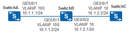
In Figure 1, SwitchA, SwitchB, and SwitchC are connected, and SwitchA has synchronized its clock with GPS.
To ensure accounting accuracy, clock synchronization is required from SwitchB and SwitchC to SwitchA.
Configuration Roadmap
The configuration roadmap is as follows:
Configure SwitchA as the NTP master clock server.
Configure the NTP unicast server/client mode to synchronize the clocks of SwitchA, SwitchB, and SwitchC. Configure SwitchA as the NTP server and SwitchB and SwitchC as NTP clients.
Enable NTP authentication to ensure NTP clock synchronization security.

When configuring NTP authentication in the unicast server/client mode, enable NTP authentication on the client, and specify the NTP server's IP address and the authentication key sent to the server. Otherwise, NTP authentication is not performed, and the NTP server and client directly synchronize their clocks.
Procedure
- Configure IP addresses for SwitchA, SwitchB, and SwitchC and ensure that they have
reachable routes to each other.
# Configure an IP address and a route on SwitchA.
<HUAWEI> system-view
[HUAWEI] sysname SwitchA
[SwitchA] vlan 100
[SwitchA-vlan100] quit
[SwitchA] interface vlanif 100
[SwitchA-Vlanif100] ip address 10.1.1.1 24
[SwitchA-Vlanif100] quit
[SwitchA] interface gigabitethernet 0/0/1
[SwitchA-GigabitEthernet0/0/1] port link-type trunk
[SwitchA-GigabitEthernet0/0/1] port trunk allow-pass vlan 100
[SwitchA-GigabitEthernet0/0/1] quit
[SwitchA] ip route-static 10.1.2.0 24 10.1.1.2
# Configure two IP addresses on SwitchB.
<HUAWEI> system-view
[HUAWEI] sysname SwitchB
[SwitchB] vlan 100
[SwitchB-vlan100] quit
[SwitchB] interface vlanif 100
[SwitchB-Vlanif100] ip address 10.1.1.2 24
[SwitchB-Vlanif100] quit
[SwitchB] vlan 10
[SwitchB-vlan10] quit
[SwitchB] interface vlanif 10
[SwitchB-Vlanif10] ip address 10.1.2.1 24
[SwitchB-Vlanif10] quit
[SwitchB] interface gigabitethernet 0/0/1
[SwitchB-GigabitEthernet0/0/1] port link-type trunk
[SwitchB-GigabitEthernet0/0/1] port trunk allow-pass vlan 100
[SwitchB-GigabitEthernet0/0/1] quit
[SwitchB] interface gigabitethernet 0/0/2
[SwitchB-GigabitEthernet0/0/2] port link-type trunk
[SwitchB-GigabitEthernet0/0/2] port trunk allow-pass vlan 10
[SwitchB-GigabitEthernet0/0/2] quit
# Configure an IP address and a route on SwitchC.
<HUAWEI> system-view
[HUAWEI] sysname SwitchC
[SwitchC] vlan 10
[SwitchC-vlan10] quit
[SwitchC] interface vlanif 10
[SwitchC-Vlanif10] ip address 10.1.2.2 24
[SwitchC-Vlanif10] quit
[SwitchC] interface gigabitethernet 0/0/1
[SwitchC-GigabitEthernet0/0/1] port link-type trunk
[SwitchC-GigabitEthernet0/0/1] port trunk allow-pass vlan 10
[SwitchC-GigabitEthernet0/0/1] quit
[SwitchC] ip route-static 10.1.1.0 24 10.1.2.1
- On SwitchA,
configure the NTP master clock and enable NTP authentication.
# Configure the local clock of SwitchA as the master clock, and set the clock stratum to 2.
[SwitchA] ntp-service refclock-master 2# Enable NTP authentication, configure the authentication key, and declare that the key is reliable.
[SwitchA] ntp-service authentication enable
[SwitchA] ntp-service authentication-keyid 42 authentication-mode hmac-sha256 cipher Hello123
[SwitchA] ntp-service reliable authentication-keyid 42
# Enable the NTP server function on SwitchA.
[SwitchA] undo ntp-service server disable - On SwitchB,
enable NTP authentication, configure the authentication key, declare
that the key is reliable, and specify SwitchA as the NTP server.
[SwitchB] ntp-service authentication enable
[SwitchB] ntp-service authentication-keyid 42 authentication-mode hmac-sha256 cipher Hello123
[SwitchB] ntp-service reliable authentication-keyid 42
[SwitchB] ntp-service unicast-server 10.1.1.1 authentication-keyid 42
- On SwitchC,
enable NTP authentication, configure the authentication key, declare
that the key is reliable, and specify SwitchA as the NTP server.
[SwitchC] ntp-service authentication enable
[SwitchC] ntp-service authentication-keyid 42 authentication-mode hmac-sha256 cipher Hello123
[SwitchC] ntp-service reliable authentication-keyid 42
[SwitchC] ntp-service unicast-server 10.1.1.1 authentication-keyid 42
- Verify the configuration.
# Check the NTP status of SwitchA.
[SwitchA] display ntp-service status
 clock status: synchronized
 clock stratum: 2
 reference clock ID: LOCAL(0)
 nominal frequency: 100.0000 Hz
 actual frequency: 100.0000 Hz
 clock precision: 2^17
 clock offset: 0.0000 ms
 root delay: 0.00 ms
 root dispersion: 10.96 ms
 peer dispersion: 10.00 ms
 reference time: 08:54:40.010 UTC Nov 22 2013(D6399696.029E9079)
 synchronization state: clock synchronized
# Check the NTP status of SwitchB. The clock status is synchronized, indicating that the clock synchronization is complete. The clock stratum is 3, which is one stratum lower than that of the NTP server SwitchA.
[SwitchB] display ntp-service status
 clock status: synchronized
 clock stratum: 3
 reference clock ID: 10.1.1.1
 nominal frequency: 100.0000 Hz
 actual frequency: 100.0000 Hz
 clock precision: 2^18
 clock offset: -1.6796 ms
 root delay: 2.71 ms
 root dispersion: 21.87 ms
 peer dispersion: 10.94 ms
 reference time: 08:54:44.160 UTC Nov 22 2013(D6399A54.29247CB7)
 synchronization state: clock synchronized
# Check the NTP status of SwitchC. The clock status is synchronized, indicating that the clock synchronization is complete. The clock stratum is 3, which is one stratum lower than that of the NTP server SwitchA.
[SwitchC] display ntp-service status
 clock status: synchronized
 clock stratum: 3
 reference clock ID: 10.1.1.1
 nominal frequency: 100.0000 Hz
 actual frequency: 100.0000 Hz
 clock precision: 2^18
 clock offset: 13.6320 ms
 root delay: 2.71 ms
 root dispersion: 2.76 ms
 peer dispersion: 10.94 ms
 reference time: 08:57:44.160 UTC Nov 22 2013(D6399E4E.052B2BFD)
 synchronization state: clock synchronized
Configuration Files
SwitchA configuration file
#
sysname SwitchA
#
vlan batch 100
#
ntp-service ipv6 server disable
ntp-service authentication enable
ntp-service authentication-keyid 42 authentication-mode hmac-sha256 cipher %^%#uLLi;!VFkMLO;SAD#:~GS=:/UzP~}1lS2'KT2,.T%^%#
ntp-service reliable authentication-keyid 42
ntp-service refclock-master 2
#
interface Vlanif100
 ip address 10.1.1.1 255.255.255.0
#
interface GigabitEthernet0/0/1
 port link-type trunk
 port trunk allow-pass vlan 100
#
ip route-static 10.1.1.0 255.255.255.0 10.1.2.1
#
return
SwitchB configuration file
#
sysname SwitchB
#
vlan batch 10 100
#
ntp-service server disable
ntp-service ipv6 server disable
ntp-service authentication enable
ntp-service authentication-keyid 42 authentication-mode hmac-sha256 cipher %^%#cVg6'G;i2*@[$uB@!^}:g$V6+~Hc}V,]M"Y/voeF%^%#
ntp-service reliable authentication-keyid 42
ntp-service unicast-server 10.1.1.1 authentication-keyid 42
#
interface Vlanif100
 ip address 10.1.1.2 255.255.255.0
#
interface Vlanif10
 ip address 10.1.2.1 255.255.255.0
#
interface GigabitEthernet0/0/1
 port link-type trunk
 port trunk allow-pass vlan 100
#
interface GigabitEthernet0/0/2
 port link-type trunk
 port trunk allow-pass vlan 10
#
return
SwitchC configuration file
#
sysname SwitchC
#
vlan batch 10
#
ntp-service server disable
ntp-service ipv6 server disable
ntp-service authentication enable
ntp-service authentication-keyid 42 authentication-mode hmac-sha256 cipher %^%#G;i2;!VFkMLO;SAD#:~GS=:/UzP~}1lS2'KT2,.T%^%#
ntp-service reliable authentication-keyid 42
ntp-service unicast-server 10.1.1.1 authentication-keyid 42
#
interface Vlanif10
 ip address 10.1.2.2 255.255.255.0
#
interface GigabitEthernet0/0/1
 port link-type trunk
 port trunk allow-pass vlan 10
#
ip route-static 10.1.1.0 255.255.255.0 10.1.2.1
#
return