Example for Configuring the NTP Symmetric Peer Mode
Networking Requirements
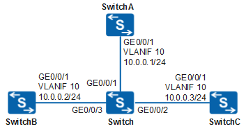
In Figure 1, SwitchA, SwitchB, and SwitchC are located within the same LAN.
To facilitate device management, all LAN devices require clock synchronization. SwitchA has synchronized its clock with GPS through a network. It is required that SwitchB and SwitchC synchronize their clocks with the clock of SwitchA.
Configuration Roadmap
The configuration roadmap is as follows:
- Configure the local clock of SwitchA as the NTP master clock.
- Configure the NTP unicast server/client mode to synchronize the clocks of SwitchB and SwitchA. Configure SwitchA as the NTP server and SwitchB as the NTP client.
Configure the NTP symmetric peer mode to synchronize the clocks of SwitchB and SwitchC. Configure SwitchC as the symmetric active peer that sends a clock synchronization request to SwitchB.
Procedure
- Configure IP addresses for SwitchA, SwitchB, and SwitchC.
Configure an IP address for each interface according to Figure 1. After the configuration is complete, SwitchA, SwitchB, and SwitchC can ping each other.
# Configure an IP address for SwitchA. The configurations of SwitchB and SwitchC are similar to the configuration of SwitchA, and are not mentioned here. For details, see the configuration files.
<HUAWEI> system-view
[HUAWEI] sysname SwitchA
[SwitchA] vlan 10
[SwitchA-vlan10] quit
[SwitchA] interface vlanif 10
[SwitchA-Vlanif10] ip address 10.0.0.1 24
[SwitchA-Vlanif10] quit
[SwitchA] interface gigabitethernet 0/0/1
[SwitchA-GigabitEthernet0/0/1] port link-type hybrid
[SwitchA-GigabitEthernet0/0/1] port hybrid untagged vlan 10
[SwitchA-GigabitEthernet0/0/1] port hybrid pvid vlan 10
[SwitchA-GigabitEthernet0/0/1] quit
- Configure Layer 2 forwarding on the Switch.
<HUAWEI> system-view
[HUAWEI] sysname Switch
[Switch] vlan 10
[Switch-vlan10] quit
[Switch] interface gigabitethernet 0/0/1
[Switch-GigabitEthernet0/0/1] port link-type hybrid
[Switch-GigabitEthernet0/0/1] port hybrid untagged vlan 10
[Switch-GigabitEthernet0/0/1] port hybrid pvid vlan 10
[Switch-GigabitEthernet0/0/1] quit
[Switch] interface gigabitethernet 0/0/2
[Switch-GigabitEthernet0/0/2] port link-type hybrid
[Switch-GigabitEthernet0/0/2] port hybrid untagged vlan 10
[Switch-GigabitEthernet0/0/2] port hybrid pvid vlan 10
[Switch-GigabitEthernet0/0/2] quit
[Switch] interface gigabitethernet 0/0/3
[Switch-GigabitEthernet0/0/3] port link-type hybrid
[Switch-GigabitEthernet0/0/3] port hybrid untagged vlan 10
[Switch-GigabitEthernet0/0/3] port hybrid pvid vlan 10
[Switch-GigabitEthernet0/0/3] quit
- Configure the NTP server/client mode.
# Configure the local clock of SwitchA as the NTP master clock, and set the clock stratum to 2.
[SwitchA] ntp-service refclock-master 2# Enable the NTP server function on SwitchA.
[SwitchA] undo ntp-service server disable# On SwitchB, specify SwitchA as its NTP server.
[SwitchB] ntp-service unicast-server 10.0.0.1# Enable the NTP server function on SwitchB.
[SwitchB] undo ntp-service server disableAfter the configuration is complete, SwitchB can synchronize its clock with the clock of SwitchA.
Check the NTP status of SwitchB. The clock status is synchronized, indicating that the clock synchronization is complete. The clock stratum is 3, which is one stratum lower than that of SwitchA.
[SwitchB] display ntp-service status clock status: synchronized clock stratum: 3 reference clock ID: 10.0.0.1 nominal frequency: 64.0029 Hz actual frequency: 64.0029 Hz clock precision: 2^7 clock offset: 0.0000 ms root delay: 62.50 ms root dispersion: 0.20 ms peer dispersion: 7.81 ms reference time: 06:52:33.465 UTC Mar 7 2006(C7B7AC31.773E89A8) synchronization state: clock set - Configure the NTP symmetric peer mode.
# On SwitchC, specify SwitchB as its symmetric passive peer.
[SwitchC] ntp-service unicast-peer 10.0.0.2# Enable the NTP server function on SwitchC.
[SwitchC] undo ntp-service server disableBecause SwitchC is not configured with a master clock and its clock stratum is lower than that of SwitchB, SwitchC synchronizes its clock with the clock of SwitchB.
- Verify the configuration.
# Check the clock status of SwitchC. The clock status is synchronized, indicating that the clock synchronization is complete. The clock stratum of SwitchC is 4, which is one stratum lower than that of the symmetric passive peer SwitchB.
[SwitchC] display ntp-service status
 clock status: synchronized
 clock stratum: 4
 reference clock ID: 10.0.0.2
 nominal frequency: 64.0029 Hz
 actual frequency: 64.0029 Hz
 clock precision: 2^7
 clock offset: 0.0000 ms
 root delay: 124.98 ms
 root dispersion: 0.15 ms
 peer dispersion: 10.96 ms
 reference time: 06:55:50.784 UTC Mar 7 2006(C7B7ACF6.C8D002E2)
 synchronization state: clock set but frequency not determined
Configuration Files
SwitchA configuration file
#
sysname SwitchA
#
vlan batch 10
#
ntp-service ipv6 server disable
ntp-service refclock-master 2
#
interface Vlanif10
 ip address 10.0.0.1 255.255.255.0
#
interface GigabitEthernet0/0/1
 port link-type hybrid
 port hybrid pvid vlan 10
 port hybrid untagged vlan 10
#
return
SwitchB configuration file
#
sysname SwitchB
#
vlan batch 10
#
ntp-service ipv6 server disable
ntp-service unicast-server 10.0.0.1
#
interface Vlanif10
 ip address 10.0.0.2 255.255.255.0
#
interface GigabitEthernet0/0/1
 port link-type hybrid
 port hybrid pvid vlan 10
 port hybrid untagged vlan 10
#
return
SwitchC configuration file
#
sysname SwitchC
#
vlan batch 10
#
ntp-service ipv6 server disable
ntp-service unicast-peer 10.0.0.2
#
interface Vlanif10
 ip address 10.0.0.3 255.255.255.0
#
interface GigabitEthernet0/0/1
 port link-type hybrid
 port hybrid pvid vlan 10
 port hybrid untagged vlan 10
#
return
-
#
sysname Switch
#
vlan batch 10
#
interface GigabitEthernet0/0/1
 port link-type hybrid
 port hybrid pvid vlan 10
 port hybrid untagged vlan 10
#
interface GigabitEthernet0/0/2
 port link-type hybrid
 port hybrid pvid vlan 10
 port hybrid untagged vlan 10
#
interface GigabitEthernet0/0/3
 port link-type hybrid
 port hybrid pvid vlan 10
 port hybrid untagged vlan 10
#
return