Example for Configuring Basic OSPF Functions
Networking Requirements
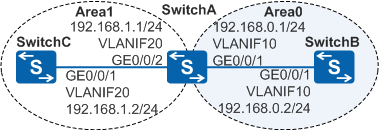
As shown in Figure 1, three switches on a network need to communicate with each other, and the entire network needs to be extended based on SwitchA and SwitchB as the service devices.
Configuration Roadmap
The configuration roadmap is as follows:
Configure VLANs for interfaces, VLANIF interfaces for the VLANs, and IP addresses for each VLANIF interface to implement communication within network segments.
Configure basic OSPF functions on each switch. Configure SwitchA as the ABR to partition the OSPF network into two areas (Area0 and Area1) so that the entire OSPF network can be extended using the area where SwitchA and SwitchB are located as the backbone area.
Procedure
- Configure VLANs for interfaces.
# Configure SwitchA. The configurations of SwitchB and SwitchC are similar to the configuration of SwitchA.
<HUAWEI> system-view
[HUAWEI] sysname SwitchA
[SwitchA] vlan batch 10 20
[SwitchA] interface gigabitethernet 0/0/1
[SwitchA-GigabitEthernet0/0/1] port link-type trunk
[SwitchA-GigabitEthernet0/0/1] port trunk allow-pass vlan 10
[SwitchA-GigabitEthernet0/0/1] quit
[SwitchA] interface gigabitethernet 0/0/2
[SwitchA-GigabitEthernet0/0/2] port link-type trunk
[SwitchA-GigabitEthernet0/0/2] port trunk allow-pass vlan 20
[SwitchA-GigabitEthernet0/0/2] quit
- Configure an IP address for each VLANIF interface.
# Configure SwitchA. The configurations of SwitchB and SwitchC are similar to the configuration of SwitchA.
[SwitchA] interface vlanif 10
[SwitchA-Vlanif10] ip address 192.168.0.1 24
[SwitchA-Vlanif10] quit
[SwitchA] interface vlanif 20
[SwitchA-Vlanif20] ip address 192.168.1.1 24
[SwitchA-Vlanif20] quit
- Configure basic OSPF functions.
# Configure SwitchA.
[SwitchA] ospf 1 router-id 10.1.1.1
[SwitchA-ospf-1] area 0
[SwitchA-ospf-1-area-0.0.0.0] network 192.168.0.0 0.0.0.255
[SwitchA-ospf-1-area-0.0.0.0] quit
[SwitchA-ospf-1] area 1
[SwitchA-ospf-1-area-0.0.0.1] network 192.168.1.0 0.0.0.255
[SwitchA-ospf-1-area-0.0.0.1] return
# Configure SwitchB.
[SwitchB] ospf 1 router-id 10.2.2.2
[SwitchB-ospf-1] area 0
[SwitchB-ospf-1-area-0.0.0.0] network 192.168.0.0 0.0.0.255
[SwitchB-ospf-1-area-0.0.0.0] return
# Configure SwitchC.
[SwitchC] ospf 1 router-id 10.3.3.3
[SwitchC-ospf-1] area 1
[SwitchC-ospf-1-area-0.0.0.1] network 192.168.1.0 0.0.0.255
[SwitchC-ospf-1-area-0.0.0.1] return
- Verify the configuration.
# Check information about OSPF neighbors on SwitchA.
<SwitchA> display ospf peer

          OSPF Process 1 with Router ID 10.1.1.1
                  Neighbors

 Area 0.0.0.0 interface 192.168.0.1(Vlanif10)'s neighbors
Router ID: 10.2.2.2      Address: 192.168.0.2
   State: Full  Mode:Nbr is  Master  Priority: 1
   DR: 192.168.0.2  BDR: 192.168.0.1   MTU: 0
   Dead timer due in 36  sec
   Retrans timer interval: 5
   Neighbor is up for 00:15:04
   Authentication Sequence: [ 0 ]

                  Neighbors

 Area 0.0.0.1 interface 192.168.1.1(Vlanif20)'s neighbors
Router ID: 10.3.3.3       Address: 192.168.1.2
   State: Full  Mode:Nbr is  Master  Priority: 1
   DR: 192.168.1.2  BDR: 192.168.1.1   MTU: 0
   Dead timer due in 39  sec
   Retrans timer interval: 5
   Neighbor is up for 00:07:32
   Authentication Sequence: [ 0 ]
# Check the OSPF routing information on SwitchC.
<SwitchC> display ospf routing

          OSPF Process 1 with Router ID 10.3.3.3
                   Routing Tables

 Routing for Network
 Destination      Cost  Type         NextHop         AdvRouter       Area
 192.168.1.0/24    1    Transit      192.168.1.2     10.3.3.3        0.0.0.1
 192.168.0.0/24    2    Inter-area   192.168.1.1     10.1.1.1        0.0.0.1

 Total Nets: 2
 Intra Area: 1  Inter Area: 1  ASE: 0  NSSA: 0
The preceding command output shows that SwitchC has an inter-area route to the network segment 192.168.0.0/24.
# Check the routing table on SwitchB, and perform the ping operation on SwitchB to test the connectivity between SwitchB and SwitchC.
<SwitchB> display ospf routing

          OSPF Process 1 with Router ID 10.2.2.2
                   Routing Tables

 Routing for Network
 Destination        Cost  Type       NextHop      AdvRouter       Area
 192.168.0.0/24     1     Transit    192.168.0.2  10.2.2.2        0.0.0.0
 192.168.1.0/24     2     Inter-area 192.168.0.1  10.1.1.1        0.0.0.0

 Total Nets: 2
 Intra Area: 1  Inter Area: 1  ASE: 0  NSSA: 0
The preceding command output shows that SwitchB has an inter-area route to the network segment 192.168.1.0/24.
# Perform the ping operation on SwitchB to test the connectivity between SwitchB and SwitchC.
<SwitchB> ping 192.168.1.2
  PING 192.168.1.2: 56  data bytes, press CTRL_C to break
    Reply from 192.168.1.2: bytes=56 Sequence=1 ttl=253 time=62 ms
    Reply from 192.168.1.2: bytes=56 Sequence=2 ttl=253 time=16 ms
    Reply from 192.168.1.2: bytes=56 Sequence=3 ttl=253 time=62 ms
    Reply from 192.168.1.2: bytes=56 Sequence=4 ttl=253 time=94 ms
    Reply from 192.168.1.2: bytes=56 Sequence=5 ttl=253 time=63 ms

  --- 192.168.1.2 ping statistics ---
    5 packet(s) transmitted
    5 packet(s) received
    0.00% packet loss
    round-trip min/avg/max = 16/59/94 ms
Configuration Files
SwitchA configuration file
#
sysname SwitchA
#
vlan batch 10 20
#
interface Vlanif10
 ip address 192.168.0.1 255.255.255.0
#
interface Vlanif20
 ip address 192.168.1.1 255.255.255.0
#
interface GigabitEthernet0/0/1
 port link-type trunk
 port trunk allow-pass vlan 10
#
interface GigabitEthernet0/0/2
 port link-type trunk
 port trunk allow-pass vlan 20
#
ospf 1 router-id 10.1.1.1
 area 0.0.0.0
  network 192.168.0.0 0.0.0.255
 area 0.0.0.1
  network 192.168.1.0 0.0.0.255
#
return
SwitchB configuration file
#
sysname SwitchB
#
vlan batch 10
#
interface Vlanif10
 ip address 192.168.0.2 255.255.255.0
#
interface GigabitEthernet0/0/1
 port link-type trunk
 port trunk allow-pass vlan 10
#
ospf 1 router-id 10.2.2.2
 area 0.0.0.0
  network 192.168.0.0 0.0.0.255
#
return
SwitchC configuration file
#
sysname SwitchC
#
vlan batch 20
#
interface Vlanif20
 ip address 192.168.1.2 255.255.255.0
#
interface GigabitEthernet0/0/1
 port link-type trunk
 port trunk allow-pass vlan 20
#
ospf 1 router-id 10.3.3.3
 area 0.0.0.1
  network 192.168.1.0 0.0.0.255
#
return