Example for Configuring OSPF DR Election
Networking Requirements
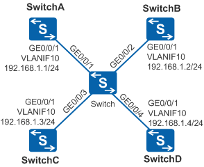
As shown in Figure 1, five switches are deployed with the intermediate Layer 2 switch connecting the other four switches running OSPF. The DR elected by default among the four switches does not meet the network requirements. SwitchA needs to be elected as the DR to exchange LSA information with other devices on the OSPF network, and SwitchC needs to be used as the backup of SwitchA. For other service demands, SwitchB needs to exchange LSA information with other devices on the OSPF network through the DR.
Configuration Roadmap
The configuration roadmap is as follows:
Configure basic OSPF functions on each switch and check the default DR election result among the four switches.
Configure the DR priorities for interfaces on SwitchA, SwitchB, and SwitchC to 100, 0, and 2 respectively. In this way, SwitchA is elected as the DR and SwitchC as the BDR, SwitchB never becomes the DR or BDR, and SwitchD uses the default DR priority and remains unchanged.
Procedure
- Configure VLANs for interfaces.
# Configure SwitchA. The configurations of Switch, SwitchB, SwitchC, and SwitchD are similar to the configuration of SwitchA.
<HUAWEI> system-view
[HUAWEI] sysname SwitchA
[SwitchA] vlan batch 10
[SwitchA] interface gigabitethernet 0/0/1
[SwitchA-GigabitEthernet0/0/1] port link-type trunk
[SwitchA-GigabitEthernet0/0/1] port trunk allow-pass vlan 10
[SwitchA-GigabitEthernet0/0/1] quit
- Configure an IP address for each VLANIF interface.
# Configure SwitchA. The configurations of SwitchB, SwitchC, and SwitchD are similar to the configuration of SwitchA.
[SwitchA] interface vlanif 10
[SwitchA-Vlanif10] ip address 192.168.1.1 24
[SwitchA-Vlanif10] quit
- Configure basic OSPF functions.
# Configure SwitchA.
[SwitchA] ospf 1 router-id 10.1.1.1
[SwitchA-ospf-1] area 0
[SwitchA-ospf-1-area-0.0.0.0] network 192.168.1.0 0.0.0.255
[SwitchA-ospf-1-area-0.0.0.0] quit
[SwitchA-ospf-1] quit
# Configure SwitchB.
[SwitchB] ospf 1 router-id 10.2.2.2
[SwitchB-ospf-1] area 0
[SwitchB-ospf-1-area-0.0.0.0] network 192.168.1.0 0.0.0.255
[SwitchB-ospf-1-area-0.0.0.0] quit
[SwitchB-ospf-1] quit
# Configure SwitchC.
[SwitchC] ospf 1 router-id 10.3.3.3
[SwitchC-ospf-1] area 0
[SwitchC-ospf-1-area-0.0.0.0] network 192.168.1.0 0.0.0.255
[SwitchC-ospf-1-area-0.0.0.0] quit
[SwitchC-ospf-1] quit
# Configure SwitchD.
[SwitchD] ospf 1 router-id 10.4.4.4
[SwitchD-ospf-1] area 0
[SwitchD-ospf-1-area-0.0.0.0] network 192.168.1.0 0.0.0.255
[SwitchD-ospf-1-area-0.0.0.0] quit
[SwitchD-ospf-1] quit
[SwitchD] quit
# Check information about OSPF neighbors on SwitchA.
[SwitchA] display ospf peer

          OSPF Process 1 with Router ID 10.1.1.1
                  Neighbors

 Area 0.0.0.0 interface 192.168.1.1(Vlanif10)'s neighbors
 Router ID: 10.2.2.2      Address: 192.168.1.2
State: 2-Way  Mode:Nbr is  Master  Priority: 1
DR: 192.168.1.4  BDR: 192.168.1.3  MTU: 0
   Dead timer due in 32  sec
   Retrans timer interval: 5
   Neighbor is up for 00:04:21
   Authentication Sequence: [ 0 ]

 Router ID: 10.3.3.3      Address: 192.168.1.3
State: Full  Mode:Nbr is  Master  Priority: 1
DR: 192.168.1.4  BDR: 192.168.1.3  MTU: 0
   Dead timer due in 37  sec
   Retrans timer interval: 5
   Neighbor is up for 00:04:06
   Authentication Sequence: [ 0 ]

 Router ID: 10.4.4.4      Address: 192.168.1.4
State: Full  Mode:Nbr is  Master  Priority: 1
DR: 192.168.1.4  BDR: 192.168.1.3  MTU: 0
   Dead timer due in 37  sec
   Retrans timer interval: 5
   Neighbor is up for 00:03:53
   Authentication Sequence: [ 0 ]
The preceding command output shows the default DR election result that SwitchD is the DR and SwitchC is the BDR. When the DR priorities are the same, the device with a greater router ID is elected as the DR.
- Set a DR priority for each switch interface.
# Configure SwitchA.
[SwitchA] interface vlanif 10
[SwitchA-Vlanif10] ospf dr-priority 100
[SwitchA-Vlanif10] quit
[SwitchA] quit
# Configure SwitchB.
[SwitchB] interface vlanif 10
[SwitchB-Vlanif10] ospf dr-priority 0
[SwitchB-Vlanif10] quit
[SwitchB] quit
# Configure SwitchC.
[SwitchC] interface vlanif 10
[SwitchC-Vlanif10] ospf dr-priority 2
[SwitchC-Vlanif10] quit
[SwitchC] quit
# Check information about OSPF neighbors on SwitchD.
<SwitchD> display ospf peer

          OSPF Process 1 with Router ID 10.4.4.4
                  Neighbors

 Area 0.0.0.0 interface 192.168.1.4(Vlanif10)'s neighbors
 Router ID: 10.1.1.1      Address: 192.168.1.1
   State: Full  Mode:Nbr is  Slave  Priority: 100
DR: 192.168.1.4  BDR: 192.168.1.3  MTU: 0
   Dead timer due in 31  sec
   Retrans timer interval: 5
   Neighbor is up for 00:11:17
   Authentication Sequence: [ 0 ]

 Router ID: 10.2.2.2      Address: 192.168.1.2
   State: Full  Mode:Nbr is  Slave  Priority: 0
DR: 192.168.1.4  BDR: 192.168.1.3  MTU: 0
   Dead timer due in 35  sec
   Retrans timer interval: 5
   Neighbor is up for 00:11:19
   Authentication Sequence: [ 0 ]

 Router ID: 10.3.3.3      Address: 192.168.1.3
   State: Full  Mode:Nbr is  Slave  Priority: 2
DR: 192.168.1.4  BDR: 192.168.1.3  MTU: 0
   Dead timer due in 33  sec
   Retrans timer interval: 5
   Neighbor is up for 00:11:15
   Authentication Sequence: [ 0 ]
The preceding command output shows that the DR election result among the four switches remains unchanged. This is because that, even if a newly added device has the highest DR priority, the device cannot immediately become the DR on the network segment after the DR and BDR election is complete. DR and BDR election is performed again only after the OSPF process is restarted.
- Restart the OSPF process.
# In the user view of each switch, run the reset ospf 1 process command to restart the OSPF process simultaneously. The simultaneous restart of the OSPF process enables each switch to participate in elections of the DR and BDR.
# Restart SwitchA.
<SwitchA> reset ospf 1 process# Restart SwitchB.
<SwitchB> reset ospf 1 process# Restart SwitchC.
<SwitchC> reset ospf 1 process# Restart SwitchD.
<SwitchD> reset ospf 1 process - Verify the configuration.
# Check information about OSPF neighbors on SwitchD.
<SwitchD> display ospf peer

          OSPF Process 1 with Router ID 10.4.4.4
                  Neighbors

 Area 0.0.0.0 interface 192.168.1.4(Vlanif10)'s neighbors
 Router ID: 10.1.1.1      Address: 192.168.1.1
State: Full  Mode:Nbr is  Slave  Priority: 100
DR: 192.168.1.1  BDR: 192.168.1.3  MTU: 0
   Dead timer due in 35  sec
   Retrans timer interval: 5
   Neighbor is up for 00:07:19
   Authentication Sequence: [ 0 ]

 Router ID: 10.2.2.2      Address: 192.168.1.2
State: 2-Way  Mode:Nbr is  Master  Priority: 0
DR: 192.168.1.1  BDR: 192.168.1.3  MTU: 0
   Dead timer due in 35  sec
   Retrans timer interval: 5
   Neighbor is up for 00:07:19
   Authentication Sequence: [ 0 ]

 Router ID: 10.3.3.3      Address: 192.168.1.3
State: Full  Mode:Nbr is  Slave  Priority: 2
DR: 192.168.1.1  BDR: 192.168.1.3  MTU: 0
   Dead timer due in 37  sec
   Retrans timer interval: 5
   Neighbor is up for 00:07:17
   Authentication Sequence: [ 0 ]
The preceding command output shows that SwitchA is elected as the DR and SwitchC as the BDR. The neighbor status between SwitchD and SwitchB is 2-Way, indicating that neither of them is the DR or BDR and they do not exchange LSA information.
Configuration Files
Switch configuration file
#
sysname Switch
#
vlan batch 10
#
interface GigabitEthernet0/0/1
 port link-type trunk
 port trunk allow-pass vlan 10
#
interface GigabitEthernet0/0/2
 port link-type trunk
 port trunk allow-pass vlan 10
#
interface GigabitEthernet0/0/3
 port link-type trunk
 port trunk allow-pass vlan 10
#
interface GigabitEthernet0/0/4
 port link-type trunk
 port trunk allow-pass vlan 10
#
return
SwitchA configuration file
#
sysname SwitchA
#
vlan batch 10
#
interface Vlanif10
 ip address 192.168.1.1 255.255.255.0
 ospf dr-priority 100
#
interface GigabitEthernet0/0/1
 port link-type trunk
 port trunk allow-pass vlan 10
#
ospf 1 router-id 10.1.1.1
 area 0.0.0.0
  network 192.168.1.0 0.0.0.255
#
return
SwitchB configuration file
#
sysname SwitchB
#
vlan batch 10
#
interface Vlanif10
 ip address 192.168.1.2 255.255.255.0
 ospf dr-priority 0
#
interface GigabitEthernet0/0/1
 port link-type trunk
 port trunk allow-pass vlan 10
#
ospf 1 router-id 10.2.2.2
 area 0.0.0.0
  network 192.168.1.0 0.0.0.255
#
return
SwitchC configuration file
#
sysname SwitchC
#
vlan batch 10
#
interface Vlanif10
 ip address 192.168.1.3 255.255.255.0
 ospf dr-priority 2
#
interface GigabitEthernet0/0/1
 port link-type trunk
 port trunk allow-pass vlan 10
#
ospf 1 router-id 10.3.3.3
 area 0.0.0.0
  network 192.168.1.0 0.0.0.255
#
return
SwitchD configuration file
#
sysname SwitchD
#
vlan batch 10
#
interface Vlanif10
 ip address 192.168.1.4 255.255.255.0
#
interface GigabitEthernet0/0/1
 port link-type trunk
 port trunk allow-pass vlan 10
#
ospf 1 router-id 10.4.4.4
 area 0.0.0.0
  network 192.168.1.0 0.0.0.255
#
return