Example for Configuring OSPF IP FRR
Networking Requirements
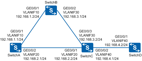
As shown in Figure 1, four switches belong to the same OSPF area. It is required that traffic forwarded by SwitchA be protected. The specific requirements are as follows:
In normal scenarios, traffic of SwitchA is forwarded over the primary link SwitchA-SwitchC.
When the primary link SwitchA-SwitchC fails, traffic is fast switched to the backup link SwitchA-SwitchB without waiting for route convergence, ensuring uninterrupted traffic forwarding.

In this scenario, ensure that all connected interfaces have STP disabled. If STP is enabled and VLANIF interfaces of switches are used to construct a Layer 3 ring network, an interface on the network will be blocked. As a result, Layer 3 services on the network cannot run normally.
Configuration Roadmap
The configuration roadmap is as follows:
Configure basic OSPF functions on each switch.
Configure OSPF IP FRR on SwitchA to ensure uninterrupted forwarding of traffic from SwitchA.
Procedure
- Configure VLANs for interfaces.
# Configure SwitchA. The configurations of SwitchB, SwitchC, and SwitchD are similar to the configuration of SwitchA.
<HUAWEI> system-view
[HUAWEI] sysname SwitchA
[SwitchA] vlan batch 10 20
[SwitchA] interface GigabitEthernet 0/0/1
[SwitchA-GigabitEthernet0/0/1] port link-type trunk
[SwitchA-GigabitEthernet0/0/1] port trunk allow-pass vlan 10
[SwitchA-GigabitEthernet0/0/1] quit
[SwitchA] interface GigabitEthernet 0/0/2
[SwitchA-GigabitEthernet0/0/2] port link-type trunk
[SwitchA-GigabitEthernet0/0/2] port trunk allow-pass vlan 20
[SwitchA-GigabitEthernet0/0/2] quit
- Configure an IP address for each VLANIF interface.
# Configure SwitchA. The configurations of SwitchB, SwitchC, and SwitchD are similar to the configuration of SwitchA.
[SwitchA] interface vlanif 10
[SwitchA-Vlanif10] ip address 192.168.1.1 24
[SwitchA-Vlanif10] quit
[SwitchA] interface vlanif 20
[SwitchA-Vlanif20] ip address 192.168.2.1 24
[SwitchA-Vlanif20] quit
- Configure basic OSPF functions.
# Configure SwitchA.
[SwitchA] ospf 1 router-id 10.1.1.1
[SwitchA-ospf-1] area 0
[SwitchA-ospf-1-area-0.0.0.0] network 192.168.1.0 0.0.0.255
[SwitchA-ospf-1-area-0.0.0.0] network 192.168.2.0 0.0.0.255
[SwitchA-ospf-1-area-0.0.0.0] quit
[SwitchA-ospf-1] quit
# Configure SwitchB.
[SwitchB] ospf 1 router-id 10.2.2.2
[SwitchB-ospf-1] area 0
[SwitchB-ospf-1-area-0.0.0.0] network 192.168.1.0 0.0.0.255
[SwitchB-ospf-1-area-0.0.0.0] network 192.168.3.0 0.0.0.255
[SwitchB-ospf-1-area-0.0.0.0] return
# Configure SwitchC.
[SwitchC] ospf 1 router-id 10.3.3.3
[SwitchC-ospf-1] area 0
[SwitchC-ospf-1-area-0.0.0.0] network 192.168.2.0 0.0.0.255
[SwitchC-ospf-1-area-0.0.0.0] network 192.168.3.0 0.0.0.255
[SwitchC-ospf-1-area-0.0.0.0] network 192.168.4.0 0.0.0.255
[SwitchC-ospf-1-area-0.0.0.0] return
# Configure SwitchD.
[SwitchD] ospf 1 router-id 10.4.4.4
[SwitchD-ospf-1] area 0
[SwitchD-ospf-1-area-0.0.0.0] network 192.168.4.0 0.0.0.255
[SwitchD-ospf-1-area-0.0.0.0] return
- Enable OSPF IP FRR on SwitchA.
# Enable OSPF IP FRR on SwitchA.
[SwitchA] ospf
[SwitchA-ospf-1] frr
[SwitchA-ospf-1-frr] loop-free-alternate
[SwitchA-ospf-1-frr] return
- Verify the configuration.
# Check information about routes from SwitchA to SwitchD. Verify that OSPF generates a backup route after OSPF IP FRR is enabled.
<SwitchA> display ospf routing 192.168.4.0

         OSPF Process 1 with Router ID 10.1.1.1

 Destination : 192.168.4.0/24
 AdverRouter : 10.4.4.4                 Area      : 0.0.0.0
 Cost        : 2                        Type      : Transit
 NextHop     : 192.168.2.2              Interface : Vlanif20
 Priority    : Low                      Age       : 00h00m10s
 Backup Nexthop : 192.168.1.2           Backup Interface: Vlanif10
 Backup Type : LFA LINK
The preceding command output shows that a backup route is generated on SwitchA.
Configuration Files
SwitchA configuration file
#
sysname SwitchA
#
vlan batch 10 20
#
interface Vlanif10
 ip address 192.168.1.1 255.255.255.0
#
interface Vlanif20
 ip address 192.168.2.1 255.255.255.0
#
interface GigabitEthernet0/0/1
 port link-type trunk
 port trunk allow-pass vlan 10
#
interface GigabitEthernet0/0/2
 port link-type trunk
 port trunk allow-pass vlan 20
#
ospf 1 router-id 10.1.1.1
 frr
  loop-free-alternate
 area 0.0.0.0
  network 192.168.1.0 0.0.0.255
  network 192.168.2.0 0.0.0.255
#
return
SwitchB configuration file
#
sysname SwitchB
#
vlan batch 10 30
#
interface Vlanif10
 ip address 192.168.1.2 255.255.255.0
#
interface Vlanif30
 ip address 192.168.3.1 255.255.255.0
#
interface GigabitEthernet0/0/1
 port link-type trunk
 port trunk allow-pass vlan 10
#
interface GigabitEthernet0/0/2
 port link-type trunk
 port trunk allow-pass vlan 30
#
ospf 1 router-id 10.2.2.2
 area 0.0.0.0
  network 192.168.1.0 0.0.0.255
  network 192.168.3.0 0.0.0.255
#
return
SwitchC configuration file
#
sysname SwitchC
#
vlan batch 20 30 40
#
interface Vlanif20
 ip address 192.168.2.2 255.255.255.0
#
interface Vlanif30
 ip address 192.168.3.2 255.255.255.0
#
interface Vlanif40
 ip address 192.168.4.1 255.255.255.0
#
interface GigabitEthernet0/0/1
 port link-type trunk
 port trunk allow-pass vlan 20
#
interface GigabitEthernet0/0/2
 port link-type trunk
 port trunk allow-pass vlan 40
#
interface GigabitEthernet0/0/3
 port link-type trunk
 port trunk allow-pass vlan 30
#
ospf 1 router-id 10.3.3.3
 area 0.0.0.0
  network 192.168.2.0 0.0.0.255
  network 192.168.3.0 0.0.0.255
  network 192.168.4.0 0.0.0.255
#
return
SwitchD configuration file
#
sysname SwitchD
#
vlan batch 40
#
interface Vlanif40
 ip address 192.168.4.2 255.255.255.0
#
interface GigabitEthernet0/0/1
 port link-type trunk
 port trunk allow-pass vlan 40
#
ospf 1 router-id 10.4.4.4
 area 0.0.0.0
  network 192.168.4.0 0.0.0.255
#
return