Example for Configuring BFD for OSPF
Networking Requirements
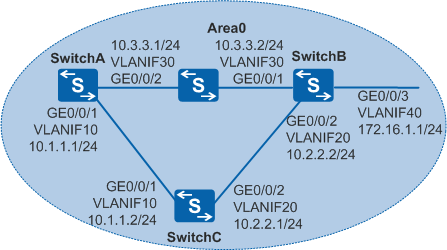
As shown in Figure 1, OSPF is running among SwitchA, SwitchB, and SwitchC, and the switch between SwitchA and SwitchB only provides transparent transmission. It is required that SwitchA and SwitchB quickly detect the status of the link between them and services be quickly switched to the backup link SwitchA-SwitchC-SwitchB when the link SwitchA-SwitchB becomes faulty.

In this scenario, ensure that all connected interfaces have STP disabled. If STP is enabled and VLANIF interfaces of switches are used to construct a Layer 3 ring network, an interface on the network will be blocked. As a result, Layer 3 services on the network cannot run normally.
Configuration Roadmap
The configuration roadmap is as follows:
Configure basic OSPF functions on each switch to implement basic connections on the OSPF network.
Configure BFD for OSPF on each switch so that services are quickly switched to the backup link if the link between SwitchA and SwitchB is faulty.
Procedure
- Configure VLANs for interfaces.
# Configure SwitchA. The configurations of SwitchB and SwitchC are similar to the configuration of SwitchA.
<HUAWEI> system-view
[HUAWEI] sysname SwitchA
[SwitchA] vlan batch 10 30
[SwitchA] interface gigabitethernet 0/0/1
[SwitchA-GigabitEthernet0/0/1] port link-type trunk
[SwitchA-GigabitEthernet0/0/1] port trunk allow-pass vlan 10
[SwitchA-GigabitEthernet0/0/1] quit
[SwitchA] interface gigabitethernet 0/0/2
[SwitchA-GigabitEthernet0/0/2] port link-type trunk
[SwitchA-GigabitEthernet0/0/2] port trunk allow-pass vlan 30
[SwitchA-GigabitEthernet0/0/2] quit
- Configure an IP address for each VLANIF interface.
# Configure SwitchA. The configurations of SwitchB and SwitchC are similar to the configuration of SwitchA.
[SwitchA] interface vlanif 10
[SwitchA-Vlanif10] ip address 10.1.1.1 24
[SwitchA-Vlanif10] quit
[SwitchA] interface vlanif 30
[SwitchA-Vlanif30] ip address 10.3.3.1 24
[SwitchA-Vlanif30] quit
- Configure basic OSPF functions.
# Configure SwitchA.
[SwitchA] ospf 1 router-id 10.10.10.1
[SwitchA-ospf-1] area 0
[SwitchA-ospf-1-area-0.0.0.0] network 10.1.1.0 0.0.0.255
[SwitchA-ospf-1-area-0.0.0.0] network 10.3.3.0 0.0.0.255
[SwitchA-ospf-1-area-0.0.0.0] quit
[SwitchA-ospf-1] quit
# Configure SwitchB.
[SwitchB] ospf 1 router-id 10.10.10.2
[SwitchB-ospf-1] area 0
[SwitchB-ospf-1-area-0.0.0.0] network 10.2.2.0 0.0.0.255
[SwitchB-ospf-1-area-0.0.0.0] network 10.3.3.0 0.0.0.255
[SwitchB-ospf-1-area-0.0.0.0] network 172.16.1.0 0.0.0.255
[SwitchB-ospf-1-area-0.0.0.0] quit
[SwitchB-ospf-1] quit
# Configure SwitchC.
[SwitchC] ospf 1 router-id 10.10.10.3
[SwitchC-ospf-1] area 0
[SwitchC-ospf-1-area-0.0.0.0] network 10.1.1.0 0.0.0.255
[SwitchC-ospf-1-area-0.0.0.0] network 10.2.2.0 0.0.0.255
[SwitchC-ospf-1-area-0.0.0.0] quit
[SwitchC-ospf-1] quit
# After the preceding configurations, run the display ospf peer command. The command output shows that adjacencies are established among SwitchA, SwitchB, and SwitchC. The following provides the command output of SwitchA:
[SwitchA] display ospf peer

          OSPF Process 1 with Router ID 10.10.10.1
                  Neighbors

 Area 0.0.0.0 interface 10.1.1.1(Vlanif10)'s neighbors
 Router ID: 10.10.10.3       Address: 10.1.1.2
   State: Full  Mode:Nbr is  Master  Priority: 1
   DR: 10.1.1.2  BDR: 10.1.1.1  MTU: 0
   Dead timer due in 38  sec
   Retrans timer interval: 5
   Neighbor is up for 00:00:15
   Authentication Sequence: [ 0 ]

                  Neighbors

 Area 0.0.0.0 interface 10.3.3.1(Vlanif30)'s neighbors
 Router ID: 10.10.10.2       Address: 10.3.3.2
   State: Full  Mode:Nbr is   Master  Priority: 1
   DR: 10.3.3.2  BDR: 10.3.3.1  MTU: 0
   Dead timer due in 25  sec
   Retrans timer interval: 5
   Neighbor is up for 00:00:59
   Authentication Sequence: [ 0 ]
# Check the OSPF routing table on SwitchA. The routing table contains the routing entries to SwitchB and SwitchC. The next-hop address of the route to the destination network segment 172.16.1.0/24 is 10.3.3.2, indicating that the traffic is transmitted over the link SwitchA→SwitchB.
[SwitchA] display ospf routing OSPF Process 1 with Router ID 10.10.10.1 Routing Tables Routing for Network Destination Cost Type NextHop AdvRouter Area 10.1.1.0/24 1 Transit 10.1.1.1 10.10.10.1 0.0.0.0 10.2.2.0/24 2 Transit 10.1.1.2 10.10.10.3 0.0.0.0 10.2.2.0/24 2 Transit 10.3.3.2 10.10.10.3 0.0.0.0 10.3.3.0/24 1 Transit 10.3.3.1 10.10.10.1 0.0.0.0 172.16.1.0/24 2 Stub 10.3.3.2 10.10.10.2 0.0.0.0 Total Nets: 5 Intra Area: 5 Inter Area: 0 ASE: 0 NSSA: 0 - Configure BFD for OSPF.
# Configure BFD for OSPF on SwitchA.
[SwitchA] bfd
[SwitchA-bfd] quit
[SwitchA] ospf 1
[SwitchA-ospf-1] bfd all-interfaces enable
[SwitchA-ospf-1] quit
# Configure BFD for OSPF on SwitchB.
[SwitchB] bfd
[SwitchB-bfd] quit
[SwitchB] ospf 1
[SwitchB-ospf-1] bfd all-interfaces enable
[SwitchB-ospf-1] quit
# Configure BFD for OSPF on SwitchC.
[SwitchC] bfd
[SwitchC-bfd] quit
[SwitchC] ospf 1
[SwitchC-ospf-1] bfd all-interfaces enable
[SwitchC-ospf-1] quit
# After the preceding configurations, run the display ospf bfd session all command on SwitchA, SwitchB, or SwitchC. Each command output shows that the BFD session status is Up. The following provides the command output of SwitchA:
[SwitchA] display ospf bfd session all OSPF Process 1 with Router ID 10.10.10.1 Area 0.0.0.0 interface 10.1.1.1(Vlanif10)'s BFD Sessions NeighborId:10.10.10.3 AreaId:0.0.0.0 Interface:Vlanif10 BFDState:up rx :1000 tx :1000 Multiplier:3 BFD Local Dis:8195 LocalIpAdd:10.1.1.1 RemoteIpAdd:10.1.1.2 Diagnostic Info:No diagnostic information Area 0.0.0.0 interface 10.3.3.1(Vlanif30)'s BFD Sessions NeighborId:10.10.10.2 AreaId:0.0.0.0 Interface:Vlanif30 BFDState:up rx :1000 tx :1000 Multiplier:3 BFD Local Dis:8194 LocalIpAdd:10.3.3.1 RemoteIpAdd:10.3.3.2 Diagnostic Info:No diagnostic information - Verify the configuration.
# Run the shutdown command on GE0/0/1 of SwitchB to simulate a link fault.
[SwitchB] interface gigabitethernet 0/0/1
[SwitchB-GigabitEthernet0/0/1] shutdown
# Check the OSPF routing table on SwitchA.
[SwitchA] display ospf routing

          OSPF Process 1 with Router ID 10.10.10.1
                   Routing Tables

 Routing for Network
 Destination        Cost  Type       NextHop         AdvRouter       Area
 10.1.1.0/24        1     Transit    10.1.1.1        10.10.10.1      0.0.0.0
 10.2.2.0/24        2     Transit    10.1.1.2        10.10.10.3      0.0.0.0
 10.3.3.0/24        1     Stub       10.3.3.1        10.10.10.1      0.0.0.0
 172.16.1.0/24      3     Stub       10.1.1.2        10.10.10.2      0.0.0.0

 Total Nets: 4
 Intra Area: 4  Inter Area: 0  ASE: 0  NSSA: 0
After the link SwitchA-SwitchB is faulty, the backup link SwitchA-SwitchC-SwitchB takes effect and the next-hop address of the route to the destination network segment 172.16.1.0/24 changes to 10.1.1.2.
Configuration Files
SwitchA configuration file
#
sysname SwitchA
#
vlan batch 10 30
#
bfd
#
interface Vlanif10
 ip address 10.1.1.1 255.255.255.0
#
interface Vlanif30
 ip address 10.3.3.1 255.255.255.0
#
interface GigabitEthernet0/0/1
 port link-type trunk
 port trunk allow-pass vlan 10
#
interface GigabitEthernet0/0/2
 port link-type trunk
 port trunk allow-pass vlan 30
#
ospf 1 router-id 10.10.10.1
 bfd all-interfaces enable
 area 0.0.0.0
  network 10.1.1.0 0.0.0.255
  network 10.3.3.0 0.0.0.255
#
return
SwitchB configuration file
#
sysname SwitchB
#
vlan batch 20 30 40
#
bfd
#
interface Vlanif20
 ip address 10.2.2.2 255.255.255.0
#
interface Vlanif30
 ip address 10.3.3.2 255.255.255.0
#
interface Vlanif40
 ip address 172.16.1.1 255.255.255.0
#
interface GigabitEthernet0/0/1
 port link-type trunk
 port trunk allow-pass vlan 30
#
interface GigabitEthernet0/0/2
 port link-type trunk
 port trunk allow-pass vlan 20
#
interface GigabitEthernet0/0/3
 port link-type trunk
 port trunk allow-pass vlan 40
#
ospf 1 router-id 10.10.10.2
 bfd all-interfaces enable
 area 0.0.0.0
  network 10.2.2.0 0.0.0.255
  network 10.3.3.0 0.0.0.255
  network 172.16.1.0 0.0.0.255
#
return
SwitchC configuration file
#
sysname SwitchC
#
vlan batch 10 20
#
bfd
#
interface Vlanif10
 ip address 10.1.1.2 255.255.255.0
#
interface Vlanif20
 ip address 10.2.2.1 255.255.255.0
#
interface GigabitEthernet0/0/1
 port link-type trunk
 port trunk allow-pass vlan 10
#
interface GigabitEthernet0/0/2
 port link-type trunk
 port trunk allow-pass vlan 20
#
ospf 1 router-id 10.10.10.3
 bfd all-interfaces enable
 area 0.0.0.0
  network 10.1.1.0 0.0.0.255
  network 10.2.2.0 0.0.0.255
#
return