Example for Configuring an OSPFv3 Stub Area
Networking Requirements
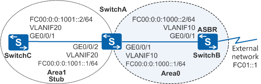
In Figure 1, OSPFv3 is running among the three switches, and the entire OSPFv3 network is divided into Area0 and Area1. SwitchA functions as an ABR and connects to Area0 and Area1, and SwitchB functions as an ASBR and connects to an OSPFv3 external network. The OSPFv3 routing table size of SwitchC needs to be reduced without affecting communication.
Configuration Roadmap
Create VLANs, add interfaces to the VLANs, and assign IPv6 addresses to VLANIF interfaces so that neighboring devices can communicate with each other.
Configure basic OSPFv3 functions on SwitchA, SwitchB, and SwitchC to ensure that there are reachable routes between OSPFv3 devices.
Configure a static route to the external network on SwitchB and import the route into the OSPFv3 routing table to ensure that there are reachable routes from the OSPFv3 network to the external network.
Configure Area1 as a stub area to reduce the OSPFv3 routing table size of SwitchC.
Configure Area1 as a totally stub area. That is, prohibit SwitchA (an ABR) in Area1 from advertising Type3 LSAs within Area1, which minimizing the OSPFv3 routing table size of SwitchC.
Procedure
- Create VLANs and add interfaces to the VLANs.
# Configure SwitchA. The configurations of SwitchB and SwitchC are similar to the configuration of SwitchA, and are not mentioned here.
<HUAWEI> system-view
[HUAWEI] sysname SwitchA
[SwitchA] vlan batch 10 20
[SwitchA] interface gigabitethernet 0/0/1
[SwitchA-GigabitEthernet0/0/1] port link-type trunk
[SwitchA-GigabitEthernet0/0/1] port trunk allow-pass vlan 10
[SwitchA-GigabitEthernet0/0/1] quit
[SwitchA] interface gigabitethernet 0/0/2
[SwitchA-GigabitEthernet0/0/2] port link-type trunk
[SwitchA-GigabitEthernet0/0/2] port trunk allow-pass vlan 20
[SwitchA-GigabitEthernet0/0/2] quit
- Configure IPv6 addresses for VLANIF interfaces to ensure that neighboring devices can communicate with each other.
# Configure SwitchA. The configurations of SwitchB and SwitchC are similar to the configuration of SwitchA, and are not mentioned here.
[SwitchA] ipv6
[SwitchA] interface vlanif 10
[SwitchA-Vlanif10] ipv6 enable
[SwitchA-Vlanif10] ipv6 address fc00:0:0:1000::1/64
[SwitchA-Vlanif10] quit
[SwitchA] interface vlanif 20
[SwitchA-Vlanif20] ipv6 enable
[SwitchA-Vlanif20] ipv6 address fc00:0:0:1001::1/64
[SwitchA-Vlanif20] quit
- Configure basic OSPFv3 functions to ensure that there are reachable routes between OSPFv3 devices.
# Configure SwitchA.
[SwitchA] ospfv3
[SwitchA-ospfv3-1] router-id 10.1.1.1
[SwitchA-ospfv3-1] quit
[SwitchA] interface vlanif 10
[SwitchA-Vlanif10] ospfv3 1 area 1
[SwitchA-Vlanif10] quit
[SwitchA] interface vlanif 20
[SwitchA-Vlanif20] ospfv3 1 area 1
[SwitchA-Vlanif20] quit
# Configure SwitchB.
[SwitchB] ospfv3
[SwitchB-ospfv3-1] router-id 10.2.2.2
[SwitchB-ospfv3-1] quit
[SwitchB] interface vlanif 10
[SwitchB-Vlanif10] ospfv3 1 area 1
[SwitchB-Vlanif10] quit
# Configure SwitchC.
[SwitchC] ospfv3
[SwitchC-ospfv3-1] router-id 10.3.3.3
[SwitchC-ospfv3-1] quit
[SwitchC] interface vlanif 20
[SwitchC-Vlanif20] ospfv3 1 area 0
[SwitchC-Vlanif20] quit
# Check the OSPFv3 neighbor status of SwitchA. The following command output shows that SwitchA has established an OSPFv3 neighbor relationship with SwitchB and SwitchC.
[SwitchA] display ospfv3 peer OSPFv3 Process (1) OSPFv3 Area (0.0.0.0) Neighbor ID Pri State Dead Time Interface Instance ID 10.2.2.2 1 Full/Backup 00:00:35 Vlanif10 0 OSPFv3 Area (0.0.0.1) Neighbor ID Pri State Dead Time Interface Instance ID 10.3.3.3 1 Full/DR 00:00:31 Vlanif20 0 - Configure a static route to the external network on SwitchB and import the route into the OSPFv3 routing table to ensure that there are reachable routes from the OSPFv3 network to the external network.
[SwitchB] ipv6 route-static fc01::1 64 null 0
[SwitchB] ospfv3
[SwitchB-ospfv3-1] import-route static type 1
[SwitchB-ospfv3-1] quit
#Check the OSPFv3 routing table of SwitchC. The following command output shows that the OSPFv3 routing table contains an AS external route.
[SwitchC] display ospfv3 routing Codes : E2 - Type 2 External, E1 - Type 1 External, IA - Inter-Area, N - NSSA, U - Uninstalled, D - Denied by Import Policy OSPFv3 Process (1) Destination Metric Next-hop IA FC00:0:0:1000::/64 2 via FE80::4E1F:CCFF:FE43:5A9E, Vlanif20 FC00:0:0:1001::/64 1 directly connected, Vlanif20 E1 FC01::/64 3 via FE80::4E1F:CCFF:FE43:5A9E, Vlanif20 - Configure Area1 as a stub area to reduce the OSPFv3 routing table size of SwitchC.
# Configure the stub area of SwitchA, and set the cost of the default route advertised to the stub area to 10.
[SwitchA] ospfv3
[SwitchA-ospfv3-1] area 1
[SwitchA-ospfv3-1-area-0.0.0.1] stub
[SwitchA-ospfv3-1-area-0.0.0.1] default-cost 10
# Configure the stub area of SwitchC.
[SwitchC] ospfv3
[SwitchC-ospfv3-1] area 1
[SwitchC-ospfv3-1-area-0.0.0.1] stub
[SwitchC-ospfv3-1-area-0.0.0.1] quit
[SwitchC-ospfv3-1] quit
- Verify the configuration.
# View the OSPFv3 routing table of SwitchC. The following command output shows that the AS external route on SwitchC is suppressed and there is a new default route in the routing table. The cost of the default route is the sum of the direct route cost and the configured cost.
[SwitchC] display ospfv3 routing Codes : E2 - Type 2 External, E1 - Type 1 External, IA - Inter-Area, N - NSSA, U - Uninstalled, D - Denied by Import Policy OSPFv3 Process (1) Destination Metric Next-hop IA ::/0 11 via FE80::4E1F:CCFF:FE43:5A9E, Vlanif20 IA FC00:0:0:1000::/64 2 via FE80::4E1F:CCFF:FE43:5A9E, Vlanif20 FC00:0:0:1001::/64 1 directly connected, Vlanif20 - Configure Area1 as a totally stub area. That is, prohibit SwitchA (an ABR) in Area1 from advertising Type3 LSAs within Area1, which minimizing the OSPFv3 routing table size of SwitchC.
# On SwitchA, configure Area1 as a totally stub area.
[SwitchA-ospfv3-1-area-0.0.0.1] stub no-summary - Verify the configuration.
# View the OSPFv3 routing table of SwitchC. The following command output shows that the OSPFv3 routing table size of SwitchC is further reduced because both the AS external route and inter-area route are suppressed.
[SwitchC] display ospfv3 routing

Codes : E2 - Type 2 External, E1 - Type 1 External, IA - Inter-Area,
        N - NSSA, U - Uninstalled, D - Denied by Import Policy

OSPFv3 Process (1)
     Destination                                               Metric
       Next-hop
  IA ::/0                                                         11
       via FE80::4E1F:CCFF:FE43:5A9E, Vlanif20
     FC00:0:0:1001::/64                                            1
       directly connected, Vlanif20
Configuration Files
SwitchA configuration file
#
sysname SwitchA
#
ipv6
#
vlan batch 10 20
#
ospfv3 1
 router-id 10.1.1.1
 area 0.0.0.1
  stub no-summary
  default-cost 10
#
interface Vlanif10
 ipv6 enable
 ipv6 address FC00:0:0:1000::1/64
 ospfv3 1 area 0.0.0.0
#
interface Vlanif20
 ipv6 enable
 ipv6 address FC00:0:0:1001::1/64
 ospfv3 1 area 0.0.0.1
#
interface GigabitEthernet0/0/1
 port link-type trunk
 port trunk allow-pass vlan 10
#
interface GigabitEthernet0/0/2
 port link-type trunk
 port trunk allow-pass vlan 20
#
return
SwitchB configuration file
#
sysname SwitchC
#
ipv6
#
vlan batch 10
#
ospfv3 1
 router-id 10.2.2.2
 import-route static type 1
#
interface Vlanif10
 ipv6 enable
 ipv6 address FC00:0:0:1000::2/64
 ospfv3 1 area 0.0.0.0
#
interface GigabitEthernet0/0/1
 port link-type trunk
 port trunk allow-pass vlan 10
#
return
SwitchC configuration file
#
sysname SwitchC
#
ipv6
#
vlan batch 20
#
ospfv3 1
 router-id 10.3.3.3
 area 0.0.0.1
  stub
#
interface Vlanif20
 ipv6 enable
 ipv6 address FC00:0:0:1001::2/64
 ospfv3 1 area 0.0.0.1
#
interface GigabitEthernet0/0/1
 port link-type trunk
 port trunk allow-pass vlan 20
#
return